- Mark as New
- Bookmark
- Subscribe
- Mute
- Subscribe to RSS Feed
- Permalink
- Report Inappropriate Content
Hi,
In “Intel® Cyclone® 10 GX Transceiver PHY User Guide” at page 100, Fig.44, the tx_clkout is 322.265625 Mhz when select PMA bus width of 32 bits (in picture, it says a number for 40 bit wide bus), and tx_coreclkin is 156.25MHz for XGMII interface as shown below,

The TX-FIFO now is working as a phase compensation mode. Read clock is NOT equal to the write clock obviously.
But, on page 102 of the same manual, in the middle paragraph there is a statement,
” For 10GBASE-R, you must achieve 0 ppm of the frequency between the read clock of TX phase compensation FIFO (PCS data) and the write clock of TX phase compensation FIFO (XGMII data in the FPGA fabric).”
What does the “0 ppm” mean here? Does it mean these two clocks should be the exactly same in frequency? If so, it looks like it does not comply with the shown in the Fig.44. Or, did I misunderstand the statement?
Anyone can help?
Appreciate a lot!
Link Copied
- Mark as New
- Bookmark
- Subscribe
- Mute
- Subscribe to RSS Feed
- Permalink
- Report Inappropriate Content
Hi,
As I understand it, you have some inquiries related to the clocking for the C10GX 10GBaseR. For your information, you should connect the tx_coreclkin with XGMII clock of 156.25MHz. I believe there might be some typo in the user guide or some of the internal blocks are not shown. Sorry for the inconvenience. However, at the top level, you would need to 156.25MHz to tx_coreclkin.
To further validate your design, it is recommended for you to create a simple test design and run through simulation to check for basic functionality before you add in more module.
Please let me know if there is any concern. Thank you.
- Mark as New
- Bookmark
- Subscribe
- Mute
- Subscribe to RSS Feed
- Permalink
- Report Inappropriate Content
Hi,
In my whole system, the receiver's phy-layer is a TI's TLK10031 which is a 10BASE-KR chip. My transmitter is a Cyclone 10 10BASE-R transceiver. Do you think it is workable together?
I found the receiving data with missing 64-bit words frequently at receiver's XGMII bus monitored by SignalTap.
Looking forward to your help.
- Mark as New
- Bookmark
- Subscribe
- Mute
- Subscribe to RSS Feed
- Permalink
- Report Inappropriate Content
Hi,
Thanks for your update. For your information, I do not have any insight on the TI's chip and could not really comment on the interop between C10GX and the TI chip. Sorry for the inconvenience.
Just to check with you on the following:
1. Based on your observation that the C10GX RX is missing 64 bits word, would you mind to further elaborate on the observation?
2. What is the IP that you are using in the C10GX device? Native PHY with 10GBase-R mode?
3. Do you observe any anomaly with the XCVR? ie CDR losing lock, rx_ready de-assertion and etc?
4. Just wonder if you have had a chance to perform a serial loopback within the C10GX device to see if you are able to get expected output? This is to help narrow down the issue location and ease debugging.
5. It would be great if you could perform a functional simulation ie in Modelsim to isolate any functional issue before moving to hardware testing.
Please let me know if there is any concern. Thank you.
Best regards,
Chee Pin
- Mark as New
- Bookmark
- Subscribe
- Mute
- Subscribe to RSS Feed
- Permalink
- Report Inappropriate Content
Hi,
Thanks for your reply.
I've tried loopback function of the transceiver locally and found the same issue, missing word or instead of FE...FE word at itself receiver output.
Yes, I use the IP of 10GBASE-R.
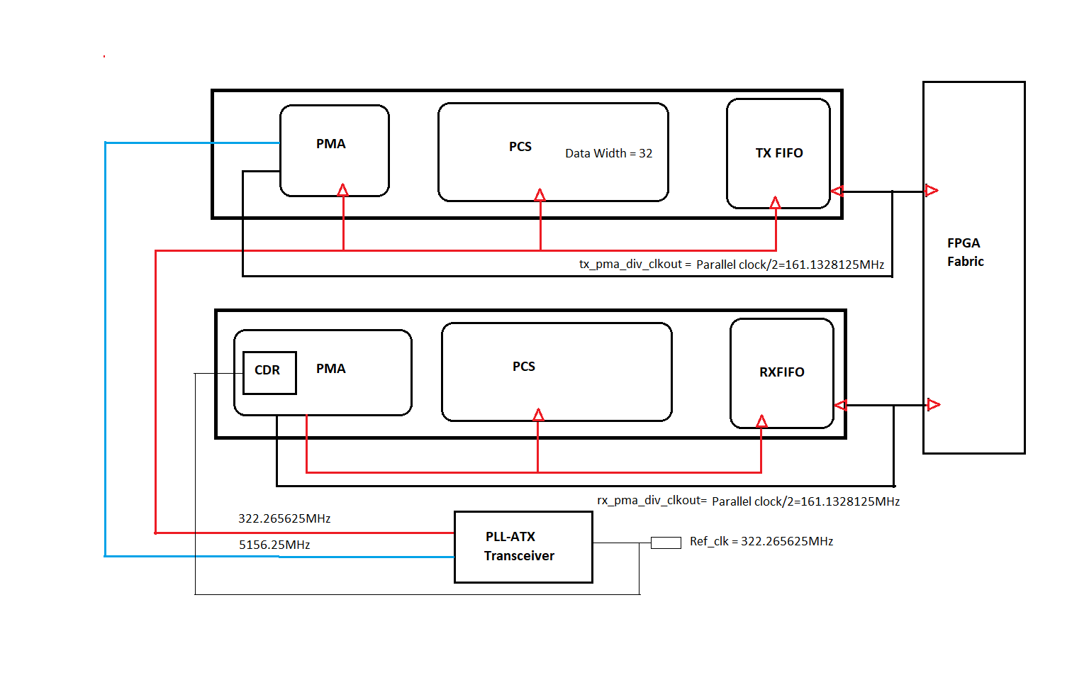
It looks like the receiving side works well but the transmitting side has problem. I just don't understand quite well about the clocking scheme for TX FIFO. Currently i am using the tx_pma_div_clkout as XGMII interface clock(half of the parallel clock frequency), shown as the attached. Do you think it is a right connection?
Could it be a problem of PMA stage as well? Do you think that Transceiver Toolkit is helpful to debug my issue? I have never used it before.
Appreciate a lot and looking forward to your further helps!
- Mark as New
- Bookmark
- Subscribe
- Mute
- Subscribe to RSS Feed
- Permalink
- Report Inappropriate Content
Hi,
Thanks for your update. With the loopback test, it helps to narrow down to within the FPGA.
To further narrow down, I would recommend you to create a simple test design and perform Modelsim simulation to help isolating any functional issue. Please help to share with me this simple test design as well so that I could further understand your IP configuration and the connection.
Regarding the clocking, for the XGMII clocking, you would require 156.25MHz to feed the tx and rx_coreclkin. Just wonder if you have had a chance to try with that instead of feeding the div_clkout?
Please let me know if there is any concern. Thank you.
Best regards,
Chee Pin
- Mark as New
- Bookmark
- Subscribe
- Mute
- Subscribe to RSS Feed
- Permalink
- Report Inappropriate Content
Thank you, Chee Pin so much for your response.
I did try the clock of 156.25MHz to clock the xgmii interfase. It was a little bit worse than the pma_div_clock, which means i got more FE...FE words.
I have no idea how to simulate the transceiver with ModelSim. If you don't mind i can give you my archived design for your further investigation to it.
I am under huge time pressure now about this project and very looking forward to getting your helps .
Thanks again.
- Mark as New
- Bookmark
- Subscribe
- Mute
- Subscribe to RSS Feed
- Permalink
- Report Inappropriate Content
Hi,
For your information, I have created a simple simulation test design with Native PHY in 10GBaseR mode. In the simulation, I can observe fixed dummy data 64'h0707...07 at the RX parallel output through loopback. Note that this design is just to show the loopback data is similar to the data sent. I am not familiar with 10GBaseR protocol required data. Sorry for the inconvenience.
You may refer to the a.v and a_tb.v in the test_example\mentor folder for top level and test bench. You may ignore the other non-relevant codes in the test bench as this was taken from a different simulation example.
To run the simulation, do the following:
1. Unzip the folder
2. Change the current working directory of Modelsim to test_example\mentor
3. Type "source msim_setup.tcl"
4. Type "ld" to start compilation
5. Type "do wave.do" to populate the waveform
6. Type "run -all" to start the simulation
Please let me know if there is any concern. Thank you.
- Mark as New
- Bookmark
- Subscribe
- Mute
- Subscribe to RSS Feed
- Permalink
- Report Inappropriate Content
Thank you, Mr. Chee Pin. I will do.
Just FYI, and let you know what i have done to my design.
1)I have used xcvr Toolkit to test my designed hardware. When set serial loopback, It shows PMA stage is working well. It turns out zero BER. So it is definitely something wrong in TX-PCS stage. It cause missing word(64-bit) or FE...FE word.
2)When i use signaltap monitoring both transmitting and receiving sides they are stable in idle mode meaning i can see stable 0707...07 word. But, when i send out a packet, it sometimes not always, like a 10% chance it loses a word or give a FEFE...FE word.
Currently i am using 644.53125MHz frequency input to xcvr refence input. Previously i used to use 322.265625MHz. Actually there is no difference.
I will let you know my simulation results. Thanks a lot for your helps.
- Mark as New
- Bookmark
- Subscribe
- Mute
- Subscribe to RSS Feed
- Permalink
- Report Inappropriate Content
Hi Chee Pin,
Great news! I found the bugs. As you mentioned, for 10XGBASE-R protocol the writing clock to TX-FIFO MUST be 156.25MHz. I used a pma-div-clock(by2) to drive it. It was wrong. Now my system is working after changed back. Thanks a lot!!!!!
BTW, in “Intel® Cyclone® 10 GX Transceiver PHY User Guide” at page 100, Fig.44 is correct except the parallel clock should be 322.265625 Mhz for 32bit width bus setting.
And, on page 102 of the same manual, in the middle paragraph there is a statement,
” For 10GBASE-R, you must achieve 0 ppm of the frequency between the read clock of TX phase compensation FIFO (PCS data) and the write clock of TX phase compensation FIFO (XGMII data in the FPGA fabric).”
This statement is misleading. "0ppm of the frequency" is not a precise wording.
Anyway, again, thank you for your help!
- Mark as New
- Bookmark
- Subscribe
- Mute
- Subscribe to RSS Feed
- Permalink
- Report Inappropriate Content
Hi,
Thanks for your update. Glad to hear that you have managed to resolved the issue. I will feedback to Factory on the documentation update required to avoid future confusion. Thank you.
- Subscribe to RSS Feed
- Mark Topic as New
- Mark Topic as Read
- Float this Topic for Current User
- Bookmark
- Subscribe
- Printer Friendly Page