Stratix V Partial Reconfiguration
Success! Subscription added.
Success! Subscription removed.
Sorry, you must verify to complete this action. Please click the verification link in your email. You may re-send via your profile.
- Intel Community
- Intel Community Knowledge Base
- Product Support Forums Knowledge Base
- FPGA Knowledge Base
- FPGA Wiki
- Stratix V Partial Reconfiguration
Stratix V Partial Reconfiguration
- Subscribe to RSS Feed
- Mark as New
- Mark as Read
- Bookmark
- Subscribe
- Printer Friendly Page
- Report Inappropriate Content
Stratix V Partial Reconfiguration
Stratix V Partial Reconfiguration Reference Design
This design is targeted at the Stratix V PCIe Development Kit: ( www.altera.com/products/devkits/altera/kit-sv-gx-host.html )
- Design Files: Media:Partial_Reconfig_Example_rev1.0_4Jan2013b.zip
The design allows reconfiguration between a 10-bit adder and a 10-bit multiplier block. Partial Reconfiguration (PR) between the multiplier and adder block (and vice versa) is initiated by using the push buttons on the board. An In-System Sources and Probes instance provides access to input values to the adder/multiplier and observe the output.This design was compiled and tested with Quartus v12.1, dp4 (device patch 4).
Please familiarize yourself with the “Design Planning for Partial Reconfiguration” section of the Quartus Handbook www.altera.com/literature/hb/qts/qts_qii51026.pdf. Register for this Altera Training to learn more about Partial Reconfiguration: www.altera.com/education/training/courses/IPR100
Design Description
The main design project is “top”, which is the multiplier version of the design. The Partial Reconfiguration (PR) adder instance is the “switch_ISSP” revision of the design. The In-System Sources and Probes instance has been preconfigured, issp_file.spf. There is also an embedded SignalTap instance in the design to allow debug and analysis of the PR process, pr_debug.stp.
Source Files:
./rtl folder: top.v, add.v, button_set.v, mult.v, my_probe_source.v*, pr_wrapper.v
.rtl/pr folder: add_rom_pr.v*, cb_interface.v, checkout_top.v, main_flow.v, mult_rom_pr.v*, pr_engine.v, pr_host.v, rom_bitstream.v
* MegaWizard generated files
Project Files:
add_rom_pr.mif, mult_rom_pr.mif, top.qsf, top.qpf, switch_ISSP.qsf, pr_debug.stp, issp_file.spf, project_compile.tcl, opt.txt, top.sdc
Output Files:
top.sof – fully compiled SRAM Object File (SOF) for multiplier / adder PR design
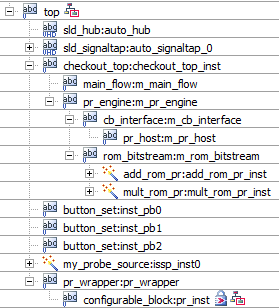
Design Hierarchy
top.v – top level design entity
sld_signaltap – SignalTap instance, pr_debug.stp
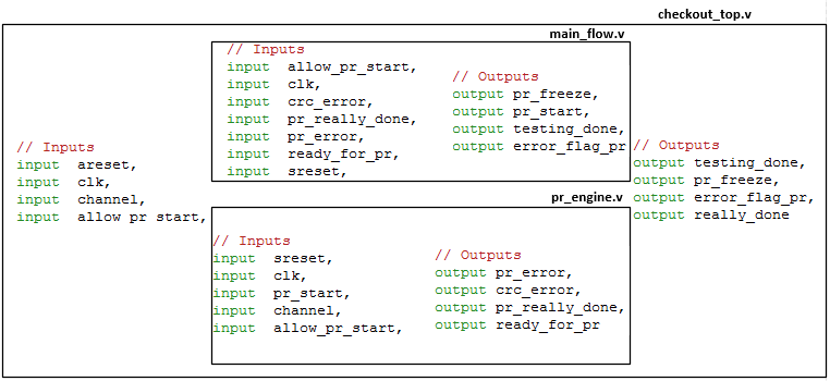
checkout_top.v – top level of reconfiguration logic
main_flow.v – state machine to control freeze, pr_start and really_done
pr_engine.v – instantiates cb_interface and rom_bitstream
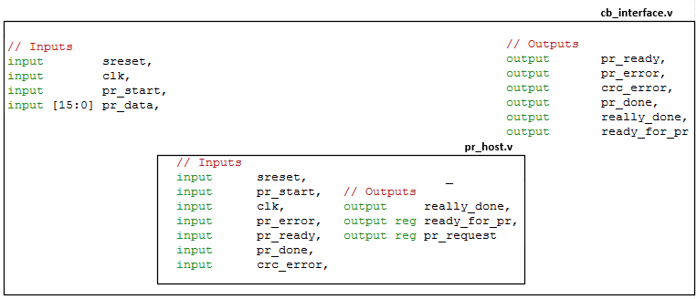
cb_interface.v – instantiates pr_host, stratixv_prblock, stratixv_crcblock
stratixv_prblock – dedicated block for PR configuration
stratixv_crcblock – dedicated block to check PR CRC
pr_host.v – controls rom_bitstream and monitors errors
rom_bitstream – block that contains ROMs for multiplier / adder instances
button_set.v – deglitch logic for the user defined push buttons
my_probe_source.v – In-System Source and Probes instance
pr_wrapper.v – PR block to freeze the inputs and outputs for the configurable_block
configurable_block.v – This block is either the 10-bit multiplier or adder
Board Pin-Out
Pin Name Location Reference Manual Page
clk Pin J23 (LVDS, 100 MHz) 32
switch_PR_image_DONE (LED0, Green) Pin J11 (2.5V) 36
switch_PR_image_ERROR (LED0, Red) Pin AH28 (2.5V) 36
user_PB2_pin Pin C7 (2.5V) 35
user_PB1_pin Pin B7 (2.5V) 35
user_PB0_pin Pin A7 (2.5V) 35
led1_g (LED1, Green) Pin U10 (2.5V) 36
led1_r (LED1, Red) Pin AG30 (2.5V) 36
Partial Reconfiguration Design Hierarchy
State Diagrams - main_flow.v
State Diagrams - rom_bitstream.v
State Diagrams - pr_host.v
Compiling the Design - Optional
A compilation script is provided to allow you to compile the projects and revisions. After extracting the “pr_example_design.7z” or “pr_example_design_noSTP.7z” file please check the following:
- Ensure you have Quartus in your path (/altera/12.1/quartus/bin64). The 64-bit executable files must be used for Stratix V
- Ensure you have the Quartus Cygwin in your path (/altera/12.1/quartus/bin64/cygwin/bin)
Open a DOS prompt and browse to the “pr_example_design” directory.
Type “quartus_sh -t project_compile.tcl”. This will compile the full design and should take about 25 minutes to complete (data from Mid-2011 Macbook Pro, i7-2820 with 16GB RAM and Windows
Working with the Example Design
1. Open Quartus v12.1, preferably with the latest patches (12.1dp4 as of this writing)
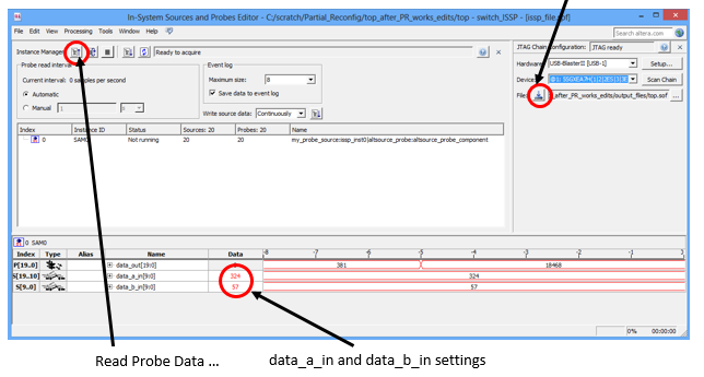
2. Open issp_file.spf, In-System Source and Probes (ISSP) file, using File, Open from Quartus. Check the “Device” settings and make sure this is pointing to the Stratix V device (highlighted in blue below, above the program button). Program the Stratix V device using the Program button
Program Button
3. Once the design is programmed into the board, note the default behavior (refer to the Stratix V Devkit Board Picture section). User LED1 will be lit red, indicating the image selected for PR is the adder image.
4. Using ISSP set data_a_in and data_b_in to some value and click the “Read Probe Data” button. Note that on initial configuration the multiplier instance is present in the design.
5. On initial configuration LED1 is red, you can press USER PB1 to change the image selection. Red is for the adder PR image and green is for the multiplier PR image. Make sure LED1 is red and now press USER PB2 to initiate reconfiguration.
6. You will see LED0 go green at this point. This indicates PR has completed and was successful. Were there a PR failure this LED would be red. Click on the “Read Probe Data” button again in the ISSP window and note the results. data_a_in and data_b_in should now be added together instead of multiplied.
7. At this point you can reconfigure back to the multiplier image by pushing USER_PB1 and ensuring LED1 is now green, selecting the multiplier image. Optional: You can also press USER_PB0, this will reset LED0. Press USER_PB2 to initiate another PR. It is likely you will notice no change in LED0 state, unless you have pressed USER_PB0 because the PR takes about 100 ms to complete.
8. Press the “Read Probe Data” button and you should see that data_a_in and data_b_in are now being multiplied again. You can continue to switch back and forth between these images.
Community support is provided Monday to Friday. Other contact methods are available here.
Intel does not verify all solutions, including but not limited to any file transfers that may appear in this community. Accordingly, Intel disclaims all express and implied warranties, including without limitation, the implied warranties of merchantability, fitness for a particular purpose, and non-infringement, as well as any warranty arising from course of performance, course of dealing, or usage in trade.
For more complete information about compiler optimizations, see our Optimization Notice.