- Mark as New
- Bookmark
- Subscribe
- Mute
- Subscribe to RSS Feed
- Permalink
- Report Inappropriate Content
Hi there,
I am attempting to create a simple Qsys system that can stream data over out over a video connection. I have decided to use the VGA interface available on the DE1-SoC boards. Eventually I want to be able to use the Qsys design to stream data out that is stored on the SDRAM of the dev kit. However I am getting stuck just getting the VGA working! I have found a video test pattern generator, an rgb resampler, the dual clock FIFO and the VGA controller but when I connect everything up and generate the Qsys system and programme it to the board, I only get a black screen for the output. Can anyone tell me where I am going wrong? (I have attached some screen shots) http://www.alteraforum.com/forum/attachment.php?attachmentid=12725&stc=1
 SDRAM u0 (
        .clk_clk       (CLOCK_50),       //   clk.clk
        .reset_reset_n (KEY), // reset.reset_n
        .wire_addr           (DRAM_ADDR),           	//  wire.addr
        .wire_ba             (DRAM_BA),             	//      .ba
        .wire_cas_n          (DRAM_CAS_N),          	//      .cas_n
        .wire_cke            (DRAM_CKE),            	//      .cke
        .wire_cs_n           (DRAM_CS_N),           	//      .cs_n
        .wire_dq             (DRAM_DQ),             	//      .dq
        .wire_dqm            ({DRAM_UDQM, DRAM_LDQM}),//      .dqm
        .wire_ras_n          (DRAM_RAS_N),          	//      .ras_n
        .wire_we_n           (DRAM_WE_N),           	//      .we_n
        .sdram_clk_clk       (DRAM_CLK),        			// sdram_clk.clk
        .vga_CLK       (VGA_CLK),       //   vga.CLK
        .vga_HS        (VGA_HS),        //      .HS
        .vga_VS        (VGA_VS),        //      .VS
        .vga_BLANK     (VGA_BLANK),     //      .BLANK
        .vga_SYNC      (VGA_SYNC),      //      .SYNC
        .vga_R         (VGA_R),         //      .R
        .vga_G         (VGA_G),         //      .G
        .vga_B         (VGA_B)          //      .B
    );
assign VGA_BLANK_N = ~VGA_BLANK;
assign VGA_SYNC_N = ~VGA_SYNC;
cheers
- Tags:
- Edit
Link Copied
- Mark as New
- Bookmark
- Subscribe
- Mute
- Subscribe to RSS Feed
- Permalink
- Report Inappropriate Content
Firstly, to isolate probable issue with connection/hardware, have you tried the examples that are included in the University program? There's a couple of examples that will generate output to the VGA.
Also, Altera forum has a strange limitation that reduces the picture attachment to low-res thumbnail... So I can't decipher much from the attachment. The top level connection looks correct to me, at least...- Mark as New
- Bookmark
- Subscribe
- Mute
- Subscribe to RSS Feed
- Permalink
- Report Inappropriate Content
Ah yes, the image has been set as a low-res thumbnail, I was hoping when it was clicked on it would be turned back into a high res image...
I have tried looking for the University Program examples for the VGA, but as of yet I've had no luck finding any VGA ones. Has anyone got a link to them or something?- Mark as New
- Bookmark
- Subscribe
- Mute
- Subscribe to RSS Feed
- Permalink
- Report Inappropriate Content
- Mark as New
- Bookmark
- Subscribe
- Mute
- Subscribe to RSS Feed
- Permalink
- Report Inappropriate Content
So I found another tutorial online for a similar application but this one uses a NIOS core. I have adapted the tutorial to use on chip memory as opposed to the SRAM they propose. However I still can't get this working!
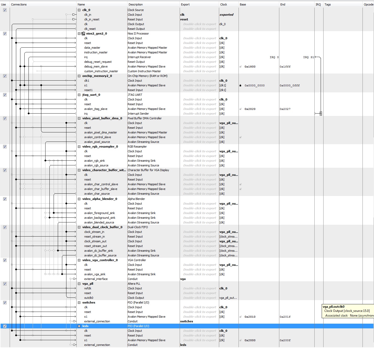
The tutorial can be found here: https://www.usna.edu/ee/ec463/notes/10_ec463_video_out_student.pdf Here is my Qsys design (hopefully a high res image) and my C source code. Note I've had to play around with it so that the writing to the onchip memory doesn't go out of bounds and cause the C program to crash.
//Base Addresses from DE2-70 Media Computer with SD# define VGA_PIXEL_BUFFER_BASE_ADR 0x0000000 // SRAM base address# define VGA_BLACK 0x0000 // Black# define VGA_RED 0xF800 // Red# define VGA_WHITE 0xFFFF // Red
# define LED_BASE 0x2000# define SW_BASE 0x2010
/* function prototypes */
    void VGA_box (int, int, int, int, short);
//Main function
int main(void)
{
    int* leds = (int*)LED_BASE;
    volatile int* sw = (int*)SW_BASE;

    /* Create a background frame */
    VGA_box (0, 0, 319, 239, VGA_RED);

    /* Create a foreground box */
    VGA_box (30, 30, 90, 90, VGA_WHITE);

    /* Create another foreground box */
    VGA_box (50, 50, 70, 70, VGA_RED);

    /* main loop */
    while(1) {
        *(leds) = *(sw);

        }// hello world
}
/* Draw a filled rectangle on the VGA monitor */
void VGA_box(int x1, int y1, int x2, int y2, short pixel_color)
{
    int offset, row, col;
        volatile int * pixel_buffer = (int *) VGA_PIXEL_BUFFER_BASE_ADR;

    while(pixel_buffer < 500){

    *(pixel_buffer) = (int) pixel_color;
    pixel_buffer = pixel_buffer + 1;
    }
    /* assume that the box coordinates are valid */
//    for (row = y1; row <= y2; row++)
//    {
//        for (col = x1; col <= x2; col++ )
//        {
//            offset = (row << 9) + col; // compute offset
//            *(pixel_buffer + offset) = (int) pixel_color; // set pixel
//        }
//    }
}
# ###########################EDIT########################################## I have added an SDRAM controller and SDRAM PLL to my design so that I can store the pixel values in the off chip memory. My base address for my SDRAM controller is set to 0x08000000 and i have ensured that the video_pixel_buffer_dma has Default buffer start address: 0x08000000 and Default back buffer start address 0x09FFFFFF (half way through the memory). However I still get a black screen on my VGA output. I believe all my top level connections are correct and that the outputs from the VGA controller can be used without any modification in the top level design entity? As Shown below:
assign VGA_BLANK_N = ~VGA_BLANK;
assign VGA_SYNC_N = ~VGA_SYNC;
 NIOS_VGA_example u0 (
	  .clk_clk       (CLOCK_50),       //   clk.clk
	  .reset_reset_n (KEY), // reset.reset_n
	  .vga_CLK       (VGA_CLK),       //   vga.CLK
	  .vga_HS        (VGA_HS),        //      .HS
	  .vga_VS        (VGA_VS),        //      .VS
	  .vga_BLANK     (VGA_BLANK),     //      .BLANK
	  .vga_SYNC      (VGA_SYNC),      //      .SYNC
	  .vga_R         (VGA_R),         //      .R
	  .vga_G         (VGA_G),         //      .G
	  .vga_B         (VGA_B),          //      .B
	  .switches_export (SW), // switches.export
	  .leds_export     (LEDR),      //     leds.export

	  .sdram_clock_clk  (DRAM_CLK),  // sdram_clock.clk
	  .sdram_wire_addr  (DRAM_ADDR),  //  sdram_wire.addr
	  .sdram_wire_ba    (DRAM_BA),    //            .ba
	  .sdram_wire_cas_n (DRAM_CAS_N), //            .cas_n
	  .sdram_wire_cke   (DRAM_CKE),   //            .cke
	  .sdram_wire_cs_n  (DRAM_CS_N),  //            .cs_n
	  .sdram_wire_dq    (DRAM_DQ),    //            .dq
	  .sdram_wire_dqm   ({DRAM_UDQM, DRAM_LDQM}),   //            .dqm
	  .sdram_wire_ras_n (DRAM_RAS_N), //            .ras_n
	  .sdram_wire_we_n  (DRAM_WE_N)   //            .we_n

 );
And due to using the off chip memory I have now use the draw box function written below:
/* Draw a filled rectangle on the VGA monitor */
void VGA_box(int x1, int y1, int x2, int y2, short pixel_color)
{
	int offset, row, col;
		volatile int * pixel_buffer = (int *) VGA_PIXEL_BUFFER_BASE_ADR;

//	while(pixel_buffer < 500){
//
//	*(pixel_buffer) = (int) pixel_color;
//	pixel_buffer = pixel_buffer + 1;
//	}
	/* assume that the box coordinates are valid */
	for (row = y1; row <= y2; row++)
	{
		for (col = x1; col <= x2; col++ )
		{
			offset = (row << 9) + col; // compute offset
			*(pixel_buffer + offset) = (int) pixel_color; // set pixel
		}
	}
}
So this is now as per the original tutorial. However I am definitely missing something here! Does anyone know what?
- Mark as New
- Bookmark
- Subscribe
- Mute
- Subscribe to RSS Feed
- Permalink
- Report Inappropriate Content
The university program VGA examples can be found as part of the Altera Monitor Program. Install this (remember to select the correct version corresponding to the Quartus version on your computer) and you can look at the examples of the Qsys and software:
https://www.altera.com/support/training/university/materials-software.html#university-program-installer I am not familiar with the examples you shared above, but if none of the examples (including the ones in Altera monitor program) works, you may have to consider the possibility of a non-working hardware. Is it possible to try the design out with a different board?- Mark as New
- Bookmark
- Subscribe
- Mute
- Subscribe to RSS Feed
- Permalink
- Report Inappropriate Content
I have the University Program installed, however it doesn't seem to have any examples with it. The only things inside the 'Universty_Program' folder are 'Computer_Systems', 'Monitor_Program', unistaller.exe and win-unistall.ico ... It is possible that, because this is a centrally managed machine, when it was installed the first time it was done incorrectly.
I have my suspicions that the hardware are fine, if i write a VGA controller in verilog then the VGA works.- Subscribe to RSS Feed
- Mark Topic as New
- Mark Topic as Read
- Float this Topic for Current User
- Bookmark
- Subscribe
- Printer Friendly Page