- Mark as New
- Bookmark
- Subscribe
- Mute
- Subscribe to RSS Feed
- Permalink
- Report Inappropriate Content
http://i714.photobucket.com/albums/ww143/littocookie/waveform.jpg
hi! I'm new to using the quartus II software and altera so i'm learning as i go along, right now I want to interface the altera board with SPI (serial interface protocol) to connect to a DAC. i'm going to send a signal of square waves into the dac and output sine waves! I have to write the code using VHDL and encoding it as a a state machine to get the same waveform on the top ( i got it from the datasheet of the DAC) here is the datasheet http://www.datasheetcatalog.org/datasheet2/c/0h9iz44c8qcc5rwpsx8ifsyw6rcy.pdf i need a constant voltage output as clock toggles, i want the state to change (every positive rising clock edge) but as I'm new to VHDL , i' dont know how to really start the "template" for a state machine in the language i have 16 states total, but the last 12 states, i want the altera to read the data how do i program it to read the data? i am writing it in terms of states/substates, using CASES.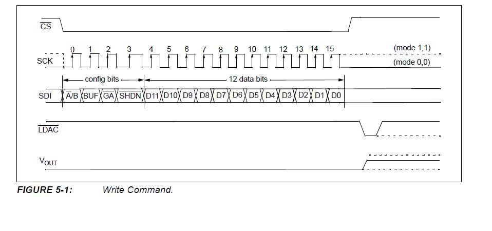
LIBRARY ieee;
USE ieee.std_logic_1164.all;
ENTITY SPI IS
    PORT( clock, reset : IN STD_LOGIC;
    SCLK, MOSI, SS :OUT STD_LOGIC);
    END SPI;

ARCHITECTURE Behaviour OF SPI IS
    TYPE State_type IS
    (AB,BUF,GA,SHDN,s11,s10,s9,s8,s7,s6,s5,s4,s3,s2,s1,s0);
    SIGNAL y: State_type;
BEGIN
    --SYNC_PROC: process (CLOCK, RESET)
    PROCESS(clock, reset)
    if reset='1' then
                state <=AB;
    elsif rising_edge(clock) then
                state <=y;
    END if;
    END process;

    PROCESS(y, clock, reset)
    BEGIN
        Case y is
                when AB=>
---continuing the state changes here....i am confused what to do
thank you!!!
Link Copied
4 Replies
- Mark as New
- Bookmark
- Subscribe
- Mute
- Subscribe to RSS Feed
- Permalink
- Report Inappropriate Content
It can basically work with a state machine. In my opinion, using a shift register and a bit counter is a more simple solution. See attached an example sending 24 bit data with SPI mode 1. Consider that your chip needs 16 bits and SPI mode 0. The code is generating a SPICLK of half the system clock, which should be suitable for most newer chips.
- Mark as New
- Bookmark
- Subscribe
- Mute
- Subscribe to RSS Feed
- Permalink
- Report Inappropriate Content
sr <= x"00" & STD_LOGIC_VECTOR What does this sentence mean?
while data : IN STD_LOGIC_VECTOR(15 downto 0); SIGNAL sr : STD_LOGIC_VECTOR(23 downto 0);- Mark as New
- Bookmark
- Subscribe
- Mute
- Subscribe to RSS Feed
- Permalink
- Report Inappropriate Content
The sentence should be sr <= x"00" & STD_LOGIC_VECTOR(data);
- Mark as New
- Bookmark
- Subscribe
- Mute
- Subscribe to RSS Feed
- Permalink
- Report Inappropriate Content
Is there missing a " ' " after the VECTOR?
Reply
Topic Options
- Subscribe to RSS Feed
- Mark Topic as New
- Mark Topic as Read
- Float this Topic for Current User
- Bookmark
- Subscribe
- Printer Friendly Page