- Mark as New
- Bookmark
- Subscribe
- Mute
- Subscribe to RSS Feed
- Permalink
- Report Inappropriate Content
Hello everybody out there using FPGAs,
I'm new to FPGA development and trying to blink a LED on the DE10-Lite board.
I carefully followed the steps on "How to program your first FPGA device" (https://software.intel.com/content/www/us/en/develop/articles/how-to-program-your-first-fpga-device.html), but the assignment of the pins on the DE10-Lite board differs as far as a understand.
I think I will have to adapt the lines
module blink (
	input wire clk, // 50MHz input clock
	output wire LED // LED ouput
);
but renaming them according to the pin assignment planner didn't really help.
I can always compile the design and upload it with the USB interface, but none of the LEDs on the board is blinking.
When compiling the design I get a warning equivalent to the following for each pin:
Warning (10034): Output port "DRAM_ADDR" at DE10_LITE_Golden_Top.v(46) has no driver
I'm not sure whether this is a problem.
I would be grateful for hints on which additional diagnostics to use in order to pin down the problem.
- Mark as New
- Bookmark
- Subscribe
- Mute
- Subscribe to RSS Feed
- Permalink
- Report Inappropriate Content
If you have a DE-10 board and you're following those instructions, you shouldn't have to change anything. I don't understand the warning you get because there is no DE10_Lite_Golden_Top.v file.
My guess is that when you went through the New Project Wizard, you either selected a project template (instead of Empty Project) or on the Family, Device, and Board Settings page, you selected a board from the Board tab instead of selecting the specific device on the Device tab. Doing either of these might create an example top-level file (DE10_Lite_Golden_Top.v) that is now getting used instead of blink.v. You can verify this is the issue by looking at the name of the top-level entity in the Project Navigator in the upper-left corner of the tool
The easiest thing to do would be to start from the beginning and follow the instructions carefully, but if you don't want to do that, go to the Project menu and select Add/Remove Files in Project. Make sure only your blink.v and .sdc file are listed. Then, with blink.v open, again from the Project menu, select Set as Top-Level Entity. Recompile and try again.
#iwork4intel
Link Copied
- Mark as New
- Bookmark
- Subscribe
- Mute
- Subscribe to RSS Feed
- Permalink
- Report Inappropriate Content
If you have a DE-10 board and you're following those instructions, you shouldn't have to change anything. I don't understand the warning you get because there is no DE10_Lite_Golden_Top.v file.
My guess is that when you went through the New Project Wizard, you either selected a project template (instead of Empty Project) or on the Family, Device, and Board Settings page, you selected a board from the Board tab instead of selecting the specific device on the Device tab. Doing either of these might create an example top-level file (DE10_Lite_Golden_Top.v) that is now getting used instead of blink.v. You can verify this is the issue by looking at the name of the top-level entity in the Project Navigator in the upper-left corner of the tool
The easiest thing to do would be to start from the beginning and follow the instructions carefully, but if you don't want to do that, go to the Project menu and select Add/Remove Files in Project. Make sure only your blink.v and .sdc file are listed. Then, with blink.v open, again from the Project menu, select Set as Top-Level Entity. Recompile and try again.
#iwork4intel
- Mark as New
- Bookmark
- Subscribe
- Mute
- Subscribe to RSS Feed
- Permalink
- Report Inappropriate Content
Thanks a lot for your answer.
This was exactly my mistake: I had chosen the "Board" tab instead of the "Device" tab and this automatically created the "DE10_Lite_Golden_Top.v" file, because I had thought this would be more accurate.
I'll try whether creating a new project the correct way solves the issue.
- Mark as New
- Bookmark
- Subscribe
- Mute
- Subscribe to RSS Feed
- Permalink
- Report Inappropriate Content
Choosing a "Device" instead of a "Board" (in the tabs of the "New Project Wizard") seems promising, but did not result in success (i.e. blinking LEDs) yet.
What could be the problem and I don't understand yet is how Quartus knows which PIN of the MAX10 corresponds to a LED or a clock:
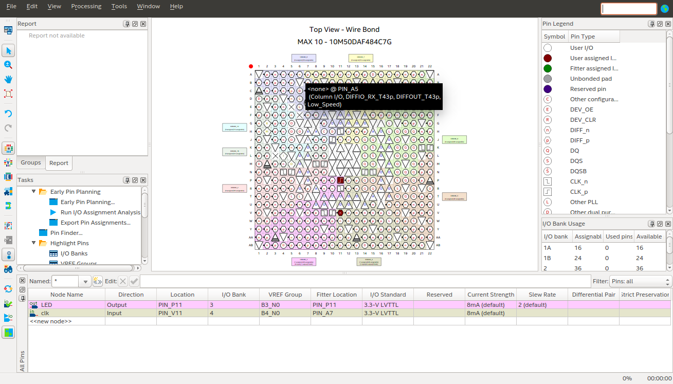
In the instructions on "How to program your first FPGA device" (https://software.intel.com/content/www/us/en/develop/articles/how-to-program-your-first-fpga-device.html), LED[0] seems to be assigned to PIN_W15 in the pin planner. I'm not sure whether this is also the case with the 10M50DAF484C7G on the DE10-Lite board. I'm particularly in doubt whether PIN_V11 on the DE10-Lite board can really be used for "clk", because the Pin Legend of the Pin Planner says its a "DIFF_n".
Please find also a screenshot of the Pin Planner below.
- Mark as New
- Bookmark
- Subscribe
- Mute
- Subscribe to RSS Feed
- Permalink
- Report Inappropriate Content
With your help I could finally get the LED to blink.
I extracted the correct assignment of the pins from Terasic's DE10-Lite manual.
- Subscribe to RSS Feed
- Mark Topic as New
- Mark Topic as Read
- Float this Topic for Current User
- Bookmark
- Subscribe
- Printer Friendly Page