- Mark as New
- Bookmark
- Subscribe
- Mute
- Subscribe to RSS Feed
- Permalink
- Report Inappropriate Content
Hi there, I'm currently doing a project for my Digital Systems course. I'm fairly new to Quartus and am attempting to compile a simple 4 Bit BCD Adder using block diagrams.
I was hoping that someone could describe to me why I cannot do this (I believe the problem area is highlighted): http://img.photobucket.com/albums/v232/MasterChief117/problem.png When I try and compile, it gives me: error: node "i[1]" is missing source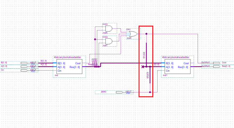
error: node "i[2]" is missing source
error: node "i[0]" is missing source
error: node "i[3]" is missing source All I want is to have I[3],I[0] at 0 permanently, and I[1],I[2] read the value the output of the OR gate. Any pointers? Thanks in advance, Andrew
Link Copied
4 Replies
- Mark as New
- Bookmark
- Subscribe
- Mute
- Subscribe to RSS Feed
- Permalink
- Report Inappropriate Content
You can do this way, for example:
Name the wire connected to the ZERO input pad as "zero" Name the OR gate output as "out_or" Draw a piece of conduit from the A[3:0] input port of adder but DON'T connect it to anything else; rename it as "zero,out_or,out_or,zero"- Mark as New
- Bookmark
- Subscribe
- Mute
- Subscribe to RSS Feed
- Permalink
- Report Inappropriate Content
In schematic design, you can use the wire and constant symbols to connect the inputs as required.
- Mark as New
- Bookmark
- Subscribe
- Mute
- Subscribe to RSS Feed
- Permalink
- Report Inappropriate Content
--- Quote Start --- In schematic design, you can use the wire and constant symbols to connect the inputs as required. --- Quote End --- Thank you very much both of you. I'm just tried the method with constant and wire. I feel like a bit of a fool asking, but I'm having trouble figuring out how to use the constant symbol. It doesn't appear to take to wires. I tried assigning it to some named wires but got compilation errors saying some of my wires didn't have inputs. Would you be able to offer a brief explanation on how to use it? Google and forum searches are coming up empty. Thanks!!
- Mark as New
- Bookmark
- Subscribe
- Mute
- Subscribe to RSS Feed
- Permalink
- Report Inappropriate Content
My suggestion was to use constant to supply constant values and wirre to connect different nets. But instead of constant, you also have GND and VCC for 0 and 1 binary values.
Schematic entry is perfect WYSIWYG, just play around and figure it out.
Reply
Topic Options
- Subscribe to RSS Feed
- Mark Topic as New
- Mark Topic as Read
- Float this Topic for Current User
- Bookmark
- Subscribe
- Printer Friendly Page