链接已复制
Hi Chow,
I have seen the pdf. So basically I saw nothing wrong with your code and the functionality work well with the simulation. Based on this equation f (x1,x2,x3) = x1x2 + x1x3 + x2x3. Figure 25 and 26 you mentioned is not the output yet, it just to specify the input and the output is on Figure 27. Below is the truth table of the equation for your second picture simulation for 0ns to 300ns and it is same as the simulation.
x1 =1 1 0
x2 =0 0 1
x3 =0 1 0
x1x2 + x1x3 + x2x3
000 =0
010 =1
010 =1
Thanks,
Regards
Thank you. That means my simulation output is correct.
Here attached the ModelSim_GUI_Introduction.pdf for version 18.0. Figure 27 is not output. But, the output in Figure 28 is not 011, as you wrote. Is Figure 28 showing a wrong output?
Hi Chow,
Sorry I was referring to this old doc http://195.130.74.161/ModelSim_GUI_Introduction.pdf but it is the same thing. According to your doc Figure 25 and 26 is same thing. Your output is y and x1,x2,x3 is just inputs. What I gave you is based on your attached simulation for second picture, the functionality worked as the truth table meaning it is correct. Also based on your doc, Figure 28 is the new simulation output for y to play around with your input x1,x2,x3 by changing their state to high or low for certain period cycle. The fact that you design work is good already :)
Thanks,
Best Regards
Thank you.
May I ask another question?
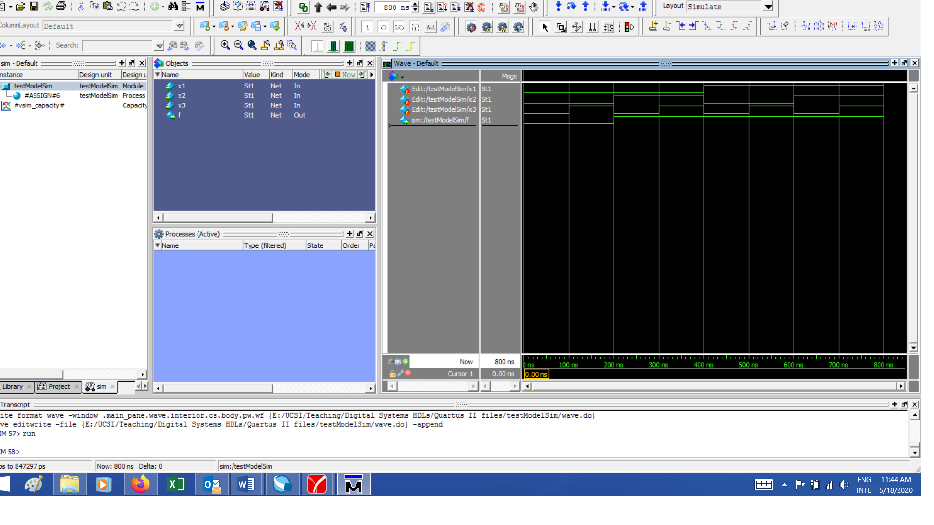
How do I open the wave file (.do) that I saved in earlier project?
For example, I saved this yesterday, but I couldn't open these inputs of x1,x2,x3 that I have keyed in for the simulation yesterday.