- Mark as New
- Bookmark
- Subscribe
- Mute
- Subscribe to RSS Feed
- Permalink
- Report Inappropriate Content
i have process I need to now implement as ROM.
process (count, outi, run) --converter
     begin
        if (run = '1') then -- run is a physical switch
        case count is       -- count is the current value of a 2 bit counter
            when "00" =>
                outi <= "1000";
            when "01" =>
                outi <= "0100";
            when "10" =>
                outi <= "0001";
            when "11" =>
                outi <= "0010";
            when others =>
                outi <= "0000";
            end case;
        end if;
     end process;
The output outi is assigned to LEDS outside the process. I have created 1 port ram and created a mif file that looks like this Addr +0 +1 +2 +3 ASCII 0 1000 0100 0001 0010 ... But I'm not sure what exactly I need to do now. I'm very to new to VHDL and FPGAs in general.
Link Copied
- Mark as New
- Bookmark
- Subscribe
- Mute
- Subscribe to RSS Feed
- Permalink
- Report Inappropriate Content
The question is, what is wrong with the current decoder?
What code have you written already, and what are the end goals? For a ROM you have a few options: 1. Use a wizard generated ROM, initialise with a .mif file 2. Define a constant and then follow the ROM template (available in the HDL coding guidelines of the Quartus Manual - and/or you can generate the template in Quartus) 3. Keep with the decoder structure, but add a clock. What do you need us to help with?- Mark as New
- Bookmark
- Subscribe
- Mute
- Subscribe to RSS Feed
- Permalink
- Report Inappropriate Content
If indeed you want to use the 1-port RAM as a ROM, you'd need to remove your decoder logic (the case statement) and instantiate the RAM in your design, attaching count to the address input of the RAM and outi to the output of the RAM.
- Mark as New
- Bookmark
- Subscribe
- Mute
- Subscribe to RSS Feed
- Permalink
- Report Inappropriate Content
--- Quote Start --- If indeed you want to use the 1-port RAM as a ROM, you'd need to remove your decoder logic (the case statement) and instantiate the RAM in your design, attaching count to the address input of the RAM and outi to the output of the RAM. --- Quote End --- You can infer a ROM from decoder logic, if it is clocked. See "inferring ROM" from the Quartus HDL coding guidelines
- Mark as New
- Bookmark
- Subscribe
- Mute
- Subscribe to RSS Feed
- Permalink
- Report Inappropriate Content
--- Quote Start --- If indeed you want to use the 1-port RAM as a ROM, you'd need to remove your decoder logic (the case statement) and instantiate the RAM in your design, attaching count to the address input of the RAM and outi to the output of the RAM. --- Quote End --- sorry for really late reply. i forgot oops. I have actually done that with block diagrams but I want to do it using only vhdl now I just don't know how I'd go about doing that
- Mark as New
- Bookmark
- Subscribe
- Mute
- Subscribe to RSS Feed
- Permalink
- Report Inappropriate Content
--- Quote Start --- sorry for really late reply. i forgot oops. I have actually done that with block diagrams but I want to do it using only vhdl now I just don't know how I'd go about doing that --- Quote End --- Have you read the quartus handbook, the section on HDL coding guidelines? https://www.altera.com/en_us/pdfs/literature/hb/qts/qts-qps-handbook.pdf Specifically, Page 12-27 - Inferring ROM Functions from HDL Code
- Mark as New
- Bookmark
- Subscribe
- Mute
- Subscribe to RSS Feed
- Permalink
- Report Inappropriate Content
I read part of it a while ago, guess i forgot about.
I found this --http://www.alteraforum.com/forum/showthread.php?t=5958-- all I actually needed to do was use component instantiation and port map to connect the ROM to the main file. Thank you for your help.- Mark as New
- Bookmark
- Subscribe
- Mute
- Subscribe to RSS Feed
- Permalink
- Report Inappropriate Content
I'm not sure if this is allowed but I have a problem with simulation.
https://www.alteraforum.com/forum/attachment.php?attachmentid=13657 The overall output of the entire program works but I want to see the internals. I get Us when I run a simulation for example I'm expecting the same output for "step" as "ROM:U1|address" U1 is a 1-port RAM that I instantiated and implemented as "ROM".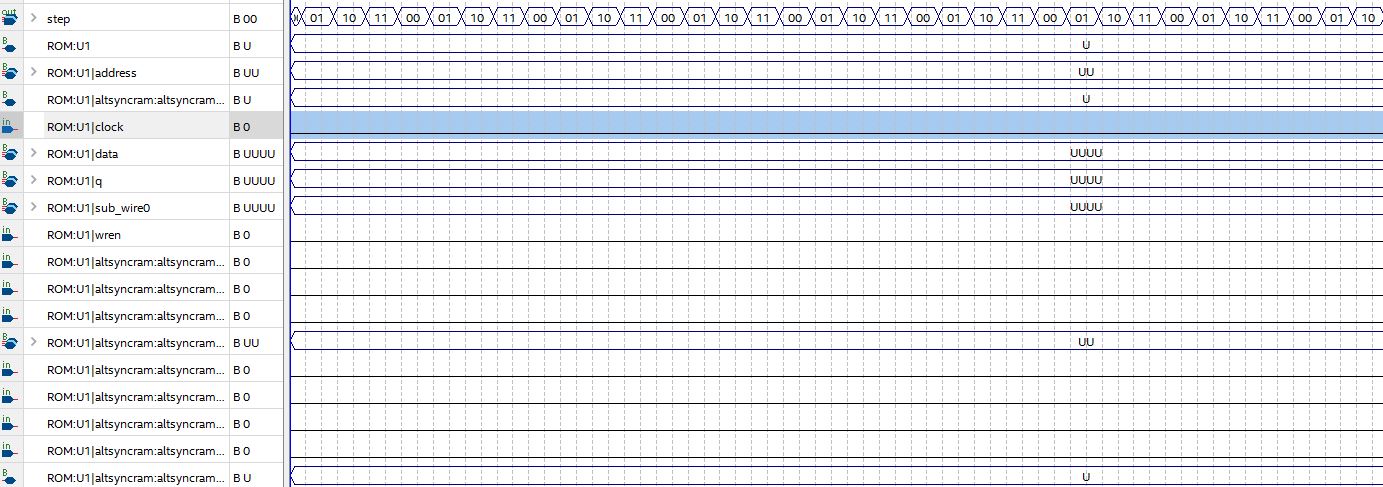
- Mark as New
- Bookmark
- Subscribe
- Mute
- Subscribe to RSS Feed
- Permalink
- Report Inappropriate Content
Without seeing the code, it is impossible to say what is wrong.
- Mark as New
- Bookmark
- Subscribe
- Mute
- Subscribe to RSS Feed
- Permalink
- Report Inappropriate Content
--- Quote Start --- Without seeing the code, it is impossible to say what is wrong. --- Quote End ---
library IEEE;
use IEEE.STD_LOGIC_1164.ALL;
use IEEE.STD_LOGIC_UNSIGNED.ALL;
entity school is
    Port ( CLOCK_50 : in std_logic;
              run : in std_logic;
              dir : in std_logic;
              step : out std_logic_vector (1 downto 0);
              led : out std_logic_vector(3 downto 0);
              slow_fast : in std_logic
     );
end school;
architecture Behavioral of school is
signal divider : std_logic_vector (22 downto 0);
signal count : std_logic_vector (1 downto 0);
signal current_clk : std_logic;
component ROM IS
    PORT
    (
        address        : IN STD_LOGIC_VECTOR (1 DOWNTO 0);
        clock        : IN STD_LOGIC  := '1';
        data        : IN STD_LOGIC_VECTOR (3 DOWNTO 0);
        wren        : IN STD_LOGIC ;
        q        : OUT STD_LOGIC_VECTOR (3 DOWNTO 0)
    );
END component;
begin
      U1 : ROM PORT MAP
(
    clock => current_clk,
    address => count,
    q => led,
    wren => '0',
    data => "0000"
);
     process (divider, CLOCK_50)
     begin
     if rising_edge(CLOCK_50) then
        divider <= divider + 1;
     end if;
     end process;

     process (run, divider, current_clk, dir, count, slow_fast )
     begin
         if slow_fast = '1' then
            current_clk <= divider(0);
         else
            current_clk <= divider(1);
         end if;

         if (rising_edge(current_clk) and run = '1') then  --
                case dir is
                    when '0' =>
                        count <= count + 1;
                    when '1' =>
                        count <= count - 1;
                    when others =>
                        count <= count + 1;
                end case;
        end if;
     end process;
step <= count;
end Behavioral;
- Mark as New
- Bookmark
- Subscribe
- Mute
- Subscribe to RSS Feed
- Permalink
- Report Inappropriate Content
Count doesnt have an initial value, or a reset value, hence it will initialise (in simulation) to 'U'
You also have other issues: 1. You should create logic divided clocks- they are prone to timing issues on hardware 2/ do not use "and" with the clock 3. its better to separate asynchronous and synchronous logic into different processes.- Mark as New
- Bookmark
- Subscribe
- Mute
- Subscribe to RSS Feed
- Permalink
- Report Inappropriate Content
--- Quote Start --- Count doesnt have an initial value, or a reset value, hence it will initialise (in simulation) to 'U' You also have other issues: 1. You should create logic divided clocks- they are prone to timing issues on hardware 2/ do not use "and" with the clock 3. its better to separate asynchronous and synchronous logic into different processes. --- Quote End --- I changed count to now be
signal count : std_logic_vector (1 downto 0) :="00"; 1. I'm sure what logic divided clock means. 2. I changed it and used if conditions instead. 3. I've done that also The output is still U for all of the U1 signals after running sim and count still initialises as U
- Mark as New
- Bookmark
- Subscribe
- Mute
- Subscribe to RSS Feed
- Permalink
- Report Inappropriate Content
Your "current_clk" is a logic generated clock, because you used logic to generate a clock
Much better to use clock enables instead.- Mark as New
- Bookmark
- Subscribe
- Mute
- Subscribe to RSS Feed
- Permalink
- Report Inappropriate Content
I made two process for different frequencies now the output looks time shifted but I don't really care about that for no. I still can't see any of U1's signals, they're all still U or UU or UUUU. is it that its just not possible or something?
- Mark as New
- Bookmark
- Subscribe
- Mute
- Subscribe to RSS Feed
- Permalink
- Report Inappropriate Content
Did you set and initial value for count? or reset it?
- Mark as New
- Bookmark
- Subscribe
- Mute
- Subscribe to RSS Feed
- Permalink
- Report Inappropriate Content
yeah signal count : std_logic_vector (1 downto 0) :="00";
- Mark as New
- Bookmark
- Subscribe
- Mute
- Subscribe to RSS Feed
- Permalink
- Report Inappropriate Content
And where is the testbench code? have you tried testing in modelsim?
- Mark as New
- Bookmark
- Subscribe
- Mute
- Subscribe to RSS Feed
- Permalink
- Report Inappropriate Content
--- Quote Start --- And where is the testbench code? have you tried testing in modelsim? --- Quote End --- I just made this
library IEEE;
use IEEE.STD_LOGIC_1164.ALL;
use IEEE.STD_LOGIC_UNSIGNED.ALL;
entity test is

end test;
architecture Behavioral of test is
component tet is
 Port ( CLOCK_50 : in std_logic;
			  run : in std_logic;
			  dir : in std_logic;
			  step : out std_logic_vector (1 downto 0);
			  led : out std_logic_vector(3 downto 0):="1000";
			  slow_fast : in std_logic
	 );
end component;
signal run_a :  std_logic := '1';
signal clk_a :  std_logic := '0';
signal dir_a : std_logic := '1';
signal slow_a :  std_logic := '0';
constant clkp : time := 20ps;
signal step_a : std_logic_vector (1 downto 0);
signal led_a : std_logic_vector (3 downto 0);
begin
	A1 : tet port map (clk_a, run_a, dir_a, step_a, led_a, slow_a );

	clk_proc : process
	begin
		  clk_a <= '0';
        wait for clkp/2;
        clk_a <= '1';
        wait for clkp/2;

	end process;

	stim_proc: process
   begin
        wait for 20 ps;
        run_a <='1';
		  dir_a <= '1';
		  slow_a <= '0';
        wait for 300 ps;
        run_a <='0';
        wait for 300 ps;
        run_a <= '1';
		  dir_a <= '0';
        wait for 300 ps;
        slow_a <= '1';
        wait for 300 ps;
  end process;
end Behavioral;
step and led show up as "UU" and "UUUU" but the signal assignments work. But if i use the university program simulation, the main program works fine (apart from the Us I get for the ROM)
- Mark as New
- Bookmark
- Subscribe
- Mute
- Subscribe to RSS Feed
- Permalink
- Report Inappropriate Content
Did you assign any values to the rom? without specifying the contents, it will simulate with all U
- Mark as New
- Bookmark
- Subscribe
- Mute
- Subscribe to RSS Feed
- Permalink
- Report Inappropriate Content
--- Quote Start --- Did you assign any values to the rom? without specifying the contents, it will simulate with all U --- Quote End --- yeah i did. It was in my first post
- Mark as New
- Bookmark
- Subscribe
- Mute
- Subscribe to RSS Feed
- Permalink
- Report Inappropriate Content
You first post shows code that would infer a rom from code. The later code shows a component called "rom" with no port called "count"
Please post ALL of your code. Why not post the project?- Subscribe to RSS Feed
- Mark Topic as New
- Mark Topic as Read
- Float this Topic for Current User
- Bookmark
- Subscribe
- Printer Friendly Page