- Mark as New
- Bookmark
- Subscribe
- Mute
- Subscribe to RSS Feed
- Permalink
- Report Inappropriate Content
I am having difficulty debugging a program on the DE1-SoC I wrote to work with the included NEC IR remote control. I thought it was my code, but then I loaded the demo program called DE1_SoC_IR from the included “cd-rom” and I am experierhaving the same issues (can't tap a signal correctly with Signal Tap). The demo is located on the disc here: “\Demonstrations\FPGA” but my question is really trying to determine what I am doing wrong in Signal Tap, I have been successfully using the tool for other test scenarios, but I can’t correctly acquire the PWM signal from the LED RX on pin AA30 using the IR remote.
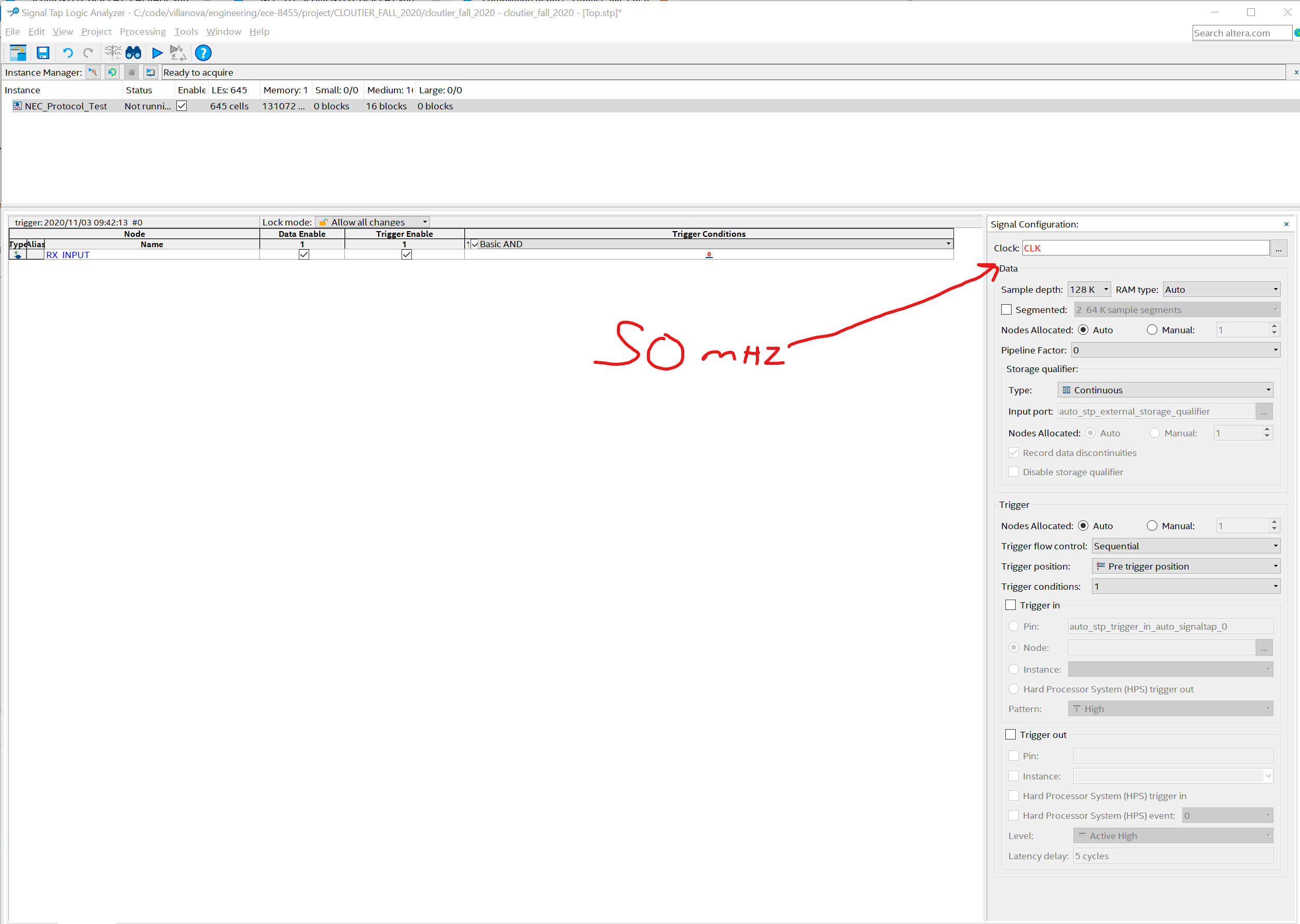
I assume most of you are familiar with the NEC Protocol… a 9ms burst followed by a 4ms window, etc. I have added a trigger on pin AA30 for Logic 0 (RX is the inverse of TX), start the analysis, and then press a button on the remote. This triggers the event BUT the signal does not go back to Logic 1 within the capture. That is, it is triggered at 0 and stays at 0 throughout the capture well past when the signal should revert to a Logic 1 (by spec it should be at 9ms).
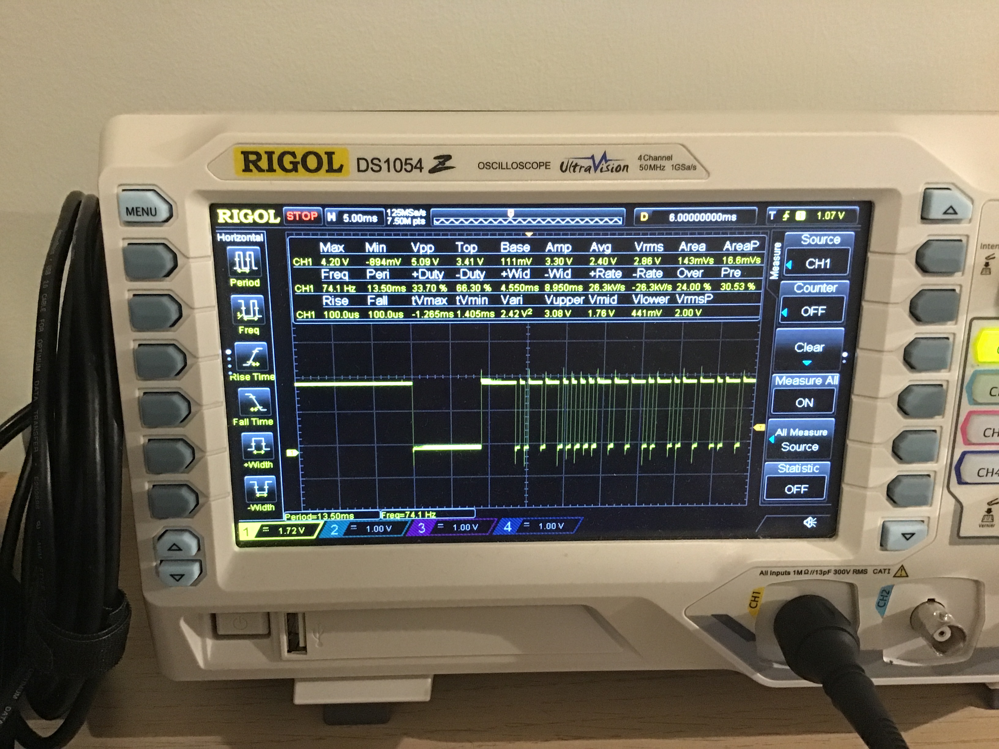
I added some images of my setup, maybe this will help. I'm really banging my head on this, so any help or pointers would be appreciated. Note: I am using a 50mhz clock and a 128k sampling depth.
Thanks in advance for any pointers you can supply.
Link Copied
- Mark as New
- Bookmark
- Subscribe
- Mute
- Subscribe to RSS Feed
- Permalink
- Report Inappropriate Content
- Mark as New
- Bookmark
- Subscribe
- Mute
- Subscribe to RSS Feed
- Permalink
- Report Inappropriate Content
One thing to be aware of with the Signal Tap waveform view is that you can basically set the scale to anything, which is weird, but that's the way it works. You have it set to "ms", but you may not be looking at ms, and with a sample depth of only 128K samples, you're definitely not seeing ms. You should always think about the waveform view in terms of samples (1 per sampling clock cycle).
If my math is correct, with a 50 MHz sampling clock (50 million cycles/sec; 50000 cycles/ms), you'd need 450000 samples (50000 x 9) to see the end of 9 ms. Your sample depth is not even close to enough to see all this, so I'm guessing your scale is incorrect in the waveform view.
I forget what the max sample depth of the logic analyzer is (128K may be the max IIRC), but if you want to see the full fall and rise of the signal, enable the storage qualifier feature to drop the samples between the falling and rising edge. You still won't see the full 9 ms though, only the beginning and ending of what you're looking for.
- Mark as New
- Bookmark
- Subscribe
- Mute
- Subscribe to RSS Feed
- Permalink
- Report Inappropriate Content
This makes great sense, thank you. I knew there must be something I was misunderstanding about how SignalTap functioned. I will try this and report back this evening.
Thank you for providing some insight!
- Mark as New
- Bookmark
- Subscribe
- Mute
- Subscribe to RSS Feed
- Permalink
- Report Inappropriate Content
Hi sstrell,
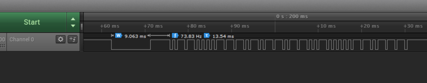
I just wanted to post a final reply. First, you are absolutely correct, the resolution I was looking for is not available for SignalTap. Thanks for pointing that out as it helped me solve my problem. In the end I purchased a logic analyzer with 100mhz resolution and it answered my question straight out of the box.
Thanks again for the help! I don't think there is a way to mark your response as the "correct answer", but if there is, please let me know and I will do so.
- Mark as New
- Bookmark
- Subscribe
- Mute
- Subscribe to RSS Feed
- Permalink
- Report Inappropriate Content
You're very welcome! Though like I said, if you need to look at an internal signal without having to bring it out to a pin (not in this case but in general), consider the storage qualifier feature.
- Subscribe to RSS Feed
- Mark Topic as New
- Mark Topic as Read
- Float this Topic for Current User
- Bookmark
- Subscribe
- Printer Friendly Page