- Mark as New
- Bookmark
- Subscribe
- Mute
- Subscribe to RSS Feed
- Permalink
- Report Inappropriate Content
If I have an 8-bit register and I concatenate an input bit to itself excluding the MSB, what does the output look like? My assumption is that the value gets bit-shifted to the left (i.e the MSB gets replaced with the bit to the right of it and the new LSB becomes the input bit). But, I am unsure.
reg [7:0] reg1 = 8'b10110010;
reg input_bit = 1'b1;
reg1 <= {reg1[6:0], input_bit}; // reg1 <= {'b0110010, 'b1}
So then the new reg1 value, as I understand it, should be 'b01100101. Is this correct?
- Tags:
- quartus
- systemverilog
- Mark as New
- Bookmark
- Subscribe
- Mute
- Subscribe to RSS Feed
- Permalink
- Report Inappropriate Content
Link Copied
- Mark as New
- Bookmark
- Subscribe
- Mute
- Subscribe to RSS Feed
- Permalink
- Report Inappropriate Content
Yes, 100% correct. Same in Verilog or SystemVerilog.
- Mark as New
- Bookmark
- Subscribe
- Mute
- Subscribe to RSS Feed
- Permalink
- Report Inappropriate Content
So in the case that I use the full register value in my concatenation operation, and add a two-bit value, then the two highest order bits get shifted out (to the left), and so on?
reg [7:0] reg1 = 8'b10110010;
reg input_bit = 2'b11;
reg1 <= {reg1[7:0], input_bit}; // reg1 <= {'b10110010, 'b11}
The new value of reg1 would be 'b11001011.
And from what I understand, the bits would be shifted right instead if I had reversed the order of the operands:
reg1 <= {input_bit,reg1[7:0]}; // reg1 <= {'b11,'b10110010}
The new value of reg1 in this case is 'b11101100.
- Mark as New
- Bookmark
- Subscribe
- Mute
- Subscribe to RSS Feed
- Permalink
- Report Inappropriate Content
Both those examples are incorrect.
In the first, input_bit is still defined as a one bit register, so assigning 2'b11 to it actually results in a value of 1'b1.
So the result assigned to reg1 in the first case would be {8'b10110010,1'b1} truncated to the rightmost 8bits is 8'b01100101.
In the second case, the value {1'b1,8'b10110010} truncated to the rightmost 8bits is 8'b10110010.
When assigning a wider bitfield on the right hand side to a smaller width destination left hand side, the upper bits are truncated.
There is no implied shift, only truncation of the upper unused bits.
If you want a shift to occur, it must be explicit using the shift operator, like: {1'b1,8'b10110010}>>2 yields 7'b1101100.
I think you meant to define reg [1:0] input_bit , that would make more sense for your example.
Then:
reg [7:0] reg1 = 8'b10110010;
reg [1:0] input_bit = 2'b11;

reg1 <= {reg1[7:0], input_bit};  // reg1 <= {8'b10110010,2'b11}
The new value of reg1 would be 8'b11001011.

reg1 <= {input_bit,reg1[7:0]};  // reg1 <= {2'b11,8'b10110010}
The new value of reg1 would be 8'b10110010 (unchanged, actually).

Also:

reg1 <= {reg1, input_bit};  // reg1 <= {8'b10110010,2'b11}
The new value of reg1 would be 8'b11001011.

reg1 <= {input_bit,reg1};  // reg1 <= {2'b11,8'b10110010}
The new value of reg1 would be 8'b10110010 (unchanged, actually).
- Mark as New
- Bookmark
- Subscribe
- Mute
- Subscribe to RSS Feed
- Permalink
- Report Inappropriate Content
You're right, I forgot to update the bitfield when copy-pasting! The bit truncation makes sense. I do wonder about your comment regarding bit shifting:
" {1'b1,8'b10110010}>>2 yields 7'b1101100. "
The left hand side yields 9'b110110010, so shouldn't right-shifting yield 9'b001101100 (same size, shifted to the right with zeros filled in as the upper two bits)?
- Mark as New
- Bookmark
- Subscribe
- Mute
- Subscribe to RSS Feed
- Permalink
- Report Inappropriate Content
You are correct on that, my mistake. I checked a few tests in a couple different verilog simulators.
Whatever the bit width is inside the { } will be the result width, zero extended left/right as necessary.
The external shift { }<<N or { }>>N value 'N' will not change the width of the resultant expression.
Zeroes will be shifted in, or shifted bits truncated as necessary.
- Mark as New
- Bookmark
- Subscribe
- Mute
- Subscribe to RSS Feed
- Permalink
- Report Inappropriate Content
Hi,
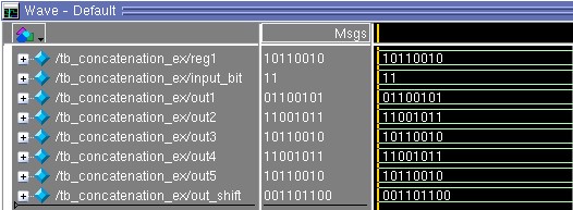
I have performed some compilation and simulation on the code in Modelsim. It verifies the discussion above. For the 2 bit-shifting to the right, zeros did fill in the upper two bits.
input [7:0] reg1;
input [1:0] input_bit;
output [7:0] out1, out2, out3, out4, out5;
output [8:0] out_shift;
//reg1 = 8'b10110010;
//input_bit = 1'b11;
assign out1 = {reg1 [6:0],input_bit [0]};
assign out2 = {reg1[7:0], input_bit};
assign out3 = {input_bit,reg1[7:0]};
assign out4 = {reg1, input_bit};
assign out5 = {input_bit,reg1};
assign out_shift = {input_bit[0], reg1}>>2;
Thanks.
Best Regards,
Ven Ting
- Mark as New
- Bookmark
- Subscribe
- Mute
- Subscribe to RSS Feed
- Permalink
- Report Inappropriate Content
Attached with the screenshot of waveform simulation result.
- Mark as New
- Bookmark
- Subscribe
- Mute
- Subscribe to RSS Feed
- Permalink
- Report Inappropriate Content
Hi,
I’m glad that your question has been addressed, I now transition this thread to community support. If you have a new question, feel free to open a new thread to get the support from Intel experts. Otherwise, the community users will continue to help you on this thread. Thank you.
Best Regards,
Ven Ting
p/s: If any answer from the community or Intel Support are helpful, please feel free to give best answer or rate 9/10 survey.
- Subscribe to RSS Feed
- Mark Topic as New
- Mark Topic as Read
- Float this Topic for Current User
- Bookmark
- Subscribe
- Printer Friendly Page