- Mark as New
- Bookmark
- Subscribe
- Mute
- Subscribe to RSS Feed
- Permalink
- Report Inappropriate Content
Hi to everybody. Can you help me about a subject. I am working on hardware modeling of the chaotic Sinus map. The equation of the sinus map is as follows. For modeling, I use ip-cores defined on IEEE 754 floating point numbers.
Xn+1=Sin(πXn)
In figure 1, you can see the schematic structure of hardware modeling Sinus Map. I am using Cyclone IV GX FPGA, DE2i-150 FPGA development board. When the 1 Ghz frequency is applied to the input of the chaotic circuit(can you see in figure 1), the result is as in figure 2. In short, the chaotic circuit does not produce right results. If I divide the 1-GHz signal (one full period of 2 nano seconds) to 2 (one full period of 4 nano seconds-250 Mhz) or 4 (1 full period of 8 nano seconds- 125 Mhz), the circuit produces the result. Pll was used to obtain 1 gigahertz frequency. The input frequency of pll is 50 megahertz.
My questions are ;
1) I wonder why the chaotic circuit does not produce results for 1 gigahertz.
2) Does the clock signal applied to the input of the circuit elements used have minimum and maximum frequency ranges?
I hope you will help me.
Kind regards.
Link Copied
- Mark as New
- Bookmark
- Subscribe
- Mute
- Subscribe to RSS Feed
- Permalink
- Report Inappropriate Content
Did you even look at the timing report? 1GHz is NOT going to be possible inside an FPGA. For a cyclone, you'll be doing good if you get >200 MHz
- Mark as New
- Bookmark
- Subscribe
- Mute
- Subscribe to RSS Feed
- Permalink
- Report Inappropriate Content
Where can I get the timing report?
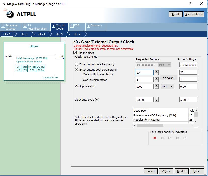
I can get 1.3 gigahertz operating frequency from pll (26x50) versus input frequency 50 megahertz. That's 26 times as much.
For example, you can see above that I cannot exceed this number in figure 3 I can synthesize this pll component on the fpga device I use.
- Mark as New
- Bookmark
- Subscribe
- Mute
- Subscribe to RSS Feed
- Permalink
- Report Inappropriate Content
Just because you can synthesise it doesnt necessarily mean it will work. The large multipliers are to allow functionality with much slower clocks (like <10MHz)
Have you provided any timing constraints in an SDC file? You need to use timequest to get a timing reeport, and would be run as part of a normal flow.
The data sheet is here:
From table 1-24, the MAx clock tree speed for the fastest devices is 500 MHz (I cant tell what speed grade device you have). But this is the clock tree, not the logic paths. The routing delays between registers is likely to bring this way down to 200MHz in a well designed system with lots of pipelining and minimal logic between registers.
Why are you trying to acheive such a high frequency? what is your target interface? this usually has a bandwidth limitation and you can work out the system clock speed you require from this.
- Mark as New
- Bookmark
- Subscribe
- Mute
- Subscribe to RSS Feed
- Permalink
- Report Inappropriate Content
- Mark as New
- Bookmark
- Subscribe
- Mute
- Subscribe to RSS Feed
- Permalink
- Report Inappropriate Content
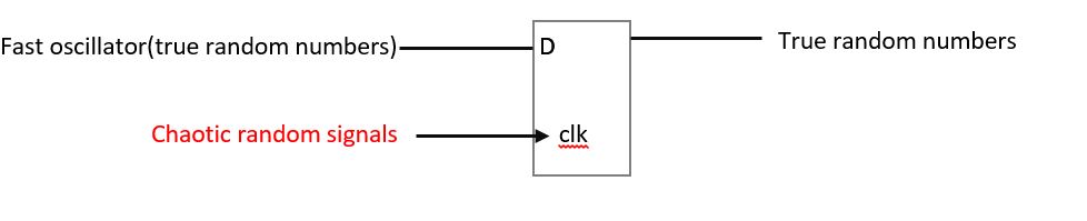
If this is what you are trying to acheive then you really do need to have a good understanding of the tinmings of the chip and its architecture. Using some "chaotic" signal as a clock is going to be difficult to deal with and difficult to control (maybe thats what you want) but you are likely to need to hand place some gates and registers.
But first, learn how timequest works.
- Mark as New
- Bookmark
- Subscribe
- Mute
- Subscribe to RSS Feed
- Permalink
- Report Inappropriate Content
Thank you so much for your help...
It looks a little confused timequest. Is there a simple and useful resource about timequest timing analysis you know?
- Mark as New
- Bookmark
- Subscribe
- Mute
- Subscribe to RSS Feed
- Permalink
- Report Inappropriate Content
- Subscribe to RSS Feed
- Mark Topic as New
- Mark Topic as Read
- Float this Topic for Current User
- Bookmark
- Subscribe
- Printer Friendly Page