- Mark as New
- Bookmark
- Subscribe
- Mute
- Subscribe to RSS Feed
- Permalink
- Report Inappropriate Content
Hello, everyone
I just wrote a very simple clock divider by 2,
and I want to add this module: clock_out.v to my top module named light.v
(from the tutorial: Using_the_SDRAM)
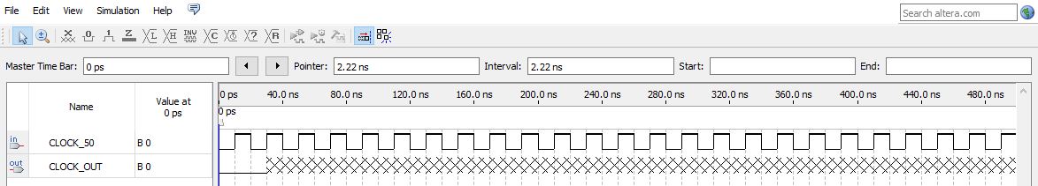
But if I running the Waveform simulation
It doesn't output a correct divided clock but an unknown signal after 2 clock,
I guess is not a very complex program to me but not always getting the right result.
I'm really confused right now.
here is my verilog source code and Waveform simulation in attachments.
Link Copied
- Mark as New
- Bookmark
- Subscribe
- Mute
- Subscribe to RSS Feed
- Permalink
- Report Inappropriate Content
Hi @FrankOuO
Sorry for the delay in response. Do you need further help regarding to this case? Do you able to solve the issue by yourself?
I would recommend to write a testbench and simulate it using the Modelsim Intel FPGA Starter Edition instead of waveform simulation.
You may checkout the webpage below for an example.
https://www.fpga4student.com/2017/08/verilog-code-for-clock-divider-on-fpga.html
Best Regards,
Richard Tan
p/s: If any answer from the community or Intel support are helpful, please feel free to give Kudos.
- Mark as New
- Bookmark
- Subscribe
- Mute
- Subscribe to RSS Feed
- Permalink
- Report Inappropriate Content
I have yet to receive any response from you to the previous question/reply/answer that I have provided but I believed that I have answered your question.
With that, I will now transition this thread to community support. If you have a new question, feel free to open a new thread to get the support from Intel experts. Otherwise, the community users will continue to help you on this thread. Thank you.
Best Regards,
Richard Tan
p/s: If any answer from the community or Intel support are helpful, please feel free to give Kudos.
- Mark as New
- Bookmark
- Subscribe
- Mute
- Subscribe to RSS Feed
- Permalink
- Report Inappropriate Content
Sorry for the late reply.
I've found out the reason why the output clock went wrongly.
I didn't assign a specific pin to the output clock so that their was no output signal.
With pin assignment, the waveform simulation and on-board test goes well.
Thank you! @RichardTanSY_Altera
Best Regards,
Frank Lee
- Subscribe to RSS Feed
- Mark Topic as New
- Mark Topic as Read
- Float this Topic for Current User
- Bookmark
- Subscribe
- Printer Friendly Page