- Mark as New
- Bookmark
- Subscribe
- Mute
- Subscribe to RSS Feed
- Permalink
- Report Inappropriate Content
Hi
I am trying to build my first qsys project. My project will be to writing/reading to a sdram memory on my DE0-nano board. Thing is I dont understand how do I work with the qsys fiels after they have been created. To be specific-I am a little confused with how do I connect the system to a higher level one and actually work with it. If anyone has a simple step by step project (without nios at this stage), that could be helpfull. I have added a picture of my system, Thank you.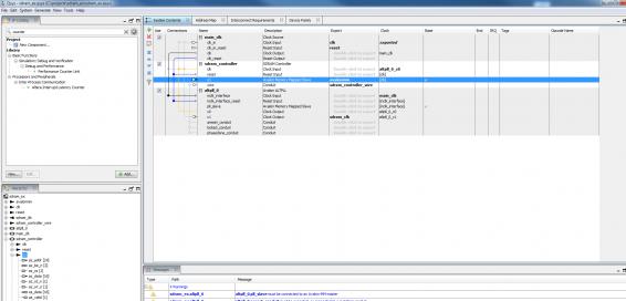
Link Copied
8 Replies
- Mark as New
- Bookmark
- Subscribe
- Mute
- Subscribe to RSS Feed
- Permalink
- Report Inappropriate Content
This thread ...
http://www.alteraforum.com/forum/showthread.php?t=45927 has a Qsys design for the DE0-nano SDRAM, along with a readme.txt file explaining it. Cheers, Dave- Mark as New
- Bookmark
- Subscribe
- Mute
- Subscribe to RSS Feed
- Permalink
- Report Inappropriate Content
Hi Dave,
Thank you for your help. I couldn't understand how do you read/write to sdram without a controller?- Mark as New
- Bookmark
- Subscribe
- Mute
- Subscribe to RSS Feed
- Permalink
- Report Inappropriate Content
--- Quote Start --- I couldn't understand how do you read/write to sdram without a controller? --- Quote End --- I'm not sure I understand your question. The Qsys system contains an SDRAM controller. The read/write interface is via the JTAG-to-Avalon-MM master bridge. If you run the synthesis script, and then open the Qsys system, you will see these components. Cheers, Dave
- Mark as New
- Bookmark
- Subscribe
- Mute
- Subscribe to RSS Feed
- Permalink
- Report Inappropriate Content
Hi Dave
I guess maybe I haven't figure out your project, since its the first time I'm working with qsys and with sdram. What I am trying to figure out is, how do I work with the controller that is given from ALTERA IP catalog. I am trying to find a state machine or an example of signal diagram to copy, but I couldn't find any. The closest thing I found was the "avalon interface specification" . If you or anyone have somthing similar to what I am asking that would great. Thank you.- Mark as New
- Bookmark
- Subscribe
- Mute
- Subscribe to RSS Feed
- Permalink
- Report Inappropriate Content
The Avalon Interface spec is exactly what you are looking for.
Part of the beauty of Qsys is that the components use standard interfaces to communicate. There are 3 main types (ignoring clock, reset and irq for the moment): avalon-mm The first is the Avalon Memory Mapped Interface. This is a way of accessing different blocks as if they are memory. You have masters and slave devices. The slave devices behave as if they are memory - so on-chip memory for example has a memory-mapped interface, so do the SDRAM controllers. But more than that, if you have a controller with configuration or status space, then it would make sense to use Av-MM for this too as you can organise the registers into a series of addressable words which starts to resemble a memory bank. The master devices are things like NIOS CPUs, DMA Controllers, etc. that need to be able to read from slave devices to control the system and move data around. There are several key signals to this (all of which are described in the interface spec): <--- Read Data ---> Write Data ---> Address Then others for flow control, byte enables, etc. (many of which are optional). Masters can control multiple slaves, and equally slaves can be controlled by multiple masters (Qsys automatically adds the arbitration logic). To make this work, when you connect them in Qsys, each slave is mapped to an address within the masters address space - for example if you had two 4kB memory blocks, one could be assigned 0x0000 to 0x0fff, and the other 0x1000 to 0x1fff - in this case the master would need at least 13bits of address width to access the full range of addresses. Clearly, slave address ranges cannot overlap within a masters address range, otherwise writes to one slave would go to the other as well. avalon-st The second interface is the Avalon Streaming interface. This is a way of transferring large amounts of data around a system quickly. In this case you have a Source and a Sink. Data flows out of the source into the sink. The beauty of this approach is you don't have the overhead of having to issue an address to a slave and wait for a response like in the Avalon-MM. Instead the sink doesn't care about addresses, it doesn't need to know where the data is coming from, just how fast it is coming in, and which clock cycles contain valid data. Streaming devices have several key signals (the ones marked opt are optional): <--- Ready (opt) ---> Valid (opt) ---> Empty (opt) ---> Data Data is obvious, that is just what you want to send. But it could have different formats - so the interface needs to specify for example what is the symbol size (e.g. 8 bits) and how many symbols are received in one clock cycle. For example if you had a 16bit data bus, but were sending 8bit symbols, you could pack 2 in the same clock cycle. If there is more than one symbol per beat (clock cycle), then you may want to also tell the sink that some symbols are empty. If say you can send 8 symbols per beat, but only have 4 to send, then there are 4 'empty' spaces in the data bus this clock cycle. Ready and Valid are flow control signals. Valid comes from the source to say in the current clock cycle there is valid data. Ready is the only signal back from the sink to say whether or not it is ready to receive data. If these two signals are present, then data is only considered sent in clock cycles where it is both valid and the sink is ready. Streaming interfaces are typically used where you need to transfer a data stream such as Ethernet packets or data from any sequential source where an address is meaningless. The great thing about these is you can build blocks to process the data on the fly. For example if you have an ADC which is spewing out samples - no address for an ADC is there? - then you could use Av-ST and have a block which could say convert the sample to a floating point number. In this case data would come in, be converted, and go out in a pipelined fashion. Streaming is basically like water flowing through pipes. conduits These are used in cases where neither of the above fit - e.g. if you have a block which has a initialised status output. This could use a conduit which could for example be routed to a physical pin where an LED is connected. They are used for so called side band signals - other information about a controller which may need to be constantly monitored by other controllers (e.g. enable signal?). others There are other signals like Clocks, Reset signals, etc. most of which are self explanatory. So essentially as you are building your own modules, try to use standard Qsys interfaces that way in you can just plug them together in Qsys with other modules and IP cores. The only thing you need to learn then is the signalling patterns of these interfaces. After than consult the data sheets for IP cores to see how they are using each interface.- Mark as New
- Bookmark
- Subscribe
- Mute
- Subscribe to RSS Feed
- Permalink
- Report Inappropriate Content
--- Quote Start --- I guess maybe I haven't figure out your project, since its the first time I'm working with qsys and with sdram. --- Quote End --- You'll need to read through the Quartus handbook :) This tutorial walks through some of the details: http://www.alterawiki.com/wiki/using_the_usb-blaster_as_an_sopc/qsys_avalon-mm_master_tutorial --- Quote Start --- What I am trying to figure out is, how do I work with the controller that is given from ALTERA IP catalog. --- Quote End --- Altera supplies all of their IP with a bus interface they call "Avalon". The interface supports reads, writes, and bursts, etc. Altera's Qsys tool allows you to connect multiple Avalon devices together, to define an address map, and then generate the interconnect (address decoding, data demultiplexing, and arbitration code). If you want to interface to the SDRAM directly, then you could create an Avalon-MM master interface state machine. Why don't you explain what you are actually trying to do. There may be Avalon components that can be used. Cheers. Dave
- Mark as New
- Bookmark
- Subscribe
- Mute
- Subscribe to RSS Feed
- Permalink
- Report Inappropriate Content
--- Quote Start --- You'll need to read through the Quartus handbook :) This tutorial walks through some of the details: http://www.alterawiki.com/wiki/using_the_usb-blaster_as_an_sopc/qsys_avalon-mm_master_tutorial If you want to interface to the SDRAM directly, then you could create an Avalon-MM master interface state machine. Why don't you explain what you are actually trying to do. There may be Avalon components that can be used. Cheers. Dave --- Quote End --- Hi all What I am trying to do is to write/read to the sdram on my DE0-nano board. I want to do it without the nios system at first. It doesn't matter what will be writen, what I care about mostly is the practice and the knoledge working with the sdram. Thats why I have been looking for a similar project, for me its the easiest way to learn.
- Mark as New
- Bookmark
- Subscribe
- Mute
- Subscribe to RSS Feed
- Permalink
- Report Inappropriate Content
--- Quote Start --- You'll need to read through the Quartus handbook :) Why don't you explain what you are actually trying to do. There may be Avalon components that can be used. Cheers. Dave --- Quote End --- Hi all What I am trying to do is to write/read to the sdram on my DE0-nano board. I want to do it without the nios system at first. It doesn't matter what will be writen, what I care about mostly is the practice and the knoledge working with the sdram. Thats why I have been looking for a similar project, for me its the easiest way to learn.
Reply
Topic Options
- Subscribe to RSS Feed
- Mark Topic as New
- Mark Topic as Read
- Float this Topic for Current User
- Bookmark
- Subscribe
- Printer Friendly Page