- Mark as New
- Bookmark
- Subscribe
- Mute
- Subscribe to RSS Feed
- Permalink
- Report Inappropriate Content
Hi Folks,
I just recently acquired an Altera PL-APU Master programming unit. (The USB version) I am wondering if anyone knows the Voltage and current rating needed for the DC Power supply to power the Programming unit. There is a standard DC power port on the back along with the USB port and a DB9 female connector. My classmate whom I bought it from, didn't have the original power supply with it. So I just want to make sure I use the right voltage rating. Any help would be appreciated. I'd love to get it up and running. I have lots of pictures of the unit if necessary for your review. Kind Regards, -GerryLink Copied
- Mark as New
- Bookmark
- Subscribe
- Mute
- Subscribe to RSS Feed
- Permalink
- Report Inappropriate Content
Any thoughts anyone? I would have thought the Altera Techs would know this no?
-Gerry- Mark as New
- Bookmark
- Subscribe
- Mute
- Subscribe to RSS Feed
- Permalink
- Report Inappropriate Content
I took the Circuit board out of the enclosure but there were no voltage markings at all around the DC input port. I'm guessing it might be around 9V DC or possibly 12 but of course I want to confirm this.
-Gerry- Mark as New
- Bookmark
- Subscribe
- Mute
- Subscribe to RSS Feed
- Permalink
- Report Inappropriate Content
Any thoughts at all ?
- Mark as New
- Bookmark
- Subscribe
- Mute
- Subscribe to RSS Feed
- Permalink
- Report Inappropriate Content
The PL-APU is essentially the same unit as the PL-ASAP2. The only difference is that it has the USB interface and therefore has no need for the LP6 Logic Programming card. This is the real old school Altera gear from the late 90's and early 2001.
-Gerry- Mark as New
- Bookmark
- Subscribe
- Mute
- Subscribe to RSS Feed
- Permalink
- Report Inappropriate Content
Here are some image Links for you to review. So I'm optimistic that someone out there could let me know what the DC voltage and Amperage requirements are for this Altera PL-APU Master programmer.
You can clearly see in the the 2nd image link below that there is no visible DC rating marked on the enclosure, so I'm in the dark here and I have not been able to find any documentation that provides the DC power supply, voltage or current ratings. Again this is the model PL-APU master programmer. (USB VERSION) http://www.digital-circuitry.com/IMAGES/webpage/MyLAB/PL-APU.jpg http://www.digital-circuitry.com/images/webpage/mylab/altera_apu_006.jpg (http://www.digital-circuitry.com/images/webpage/mylab/altera_apu_006.jpg) http://www.digital-circuitry.com/images/webpage/mylab/altera_apu_003.jpg (http://www.digital-circuitry.com/images/webpage/mylab/altera_apu_003.jpg) http://www.digital-circuitry.com/images/webpage/mylab/altera_apu_010.jpg (http://www.digital-circuitry.com/images/webpage/mylab/altera_apu_010.jpg) http://www.digital-circuitry.com/images/webpage/mylab/altera_apu_018.jpg (http://www.digital-circuitry.com/images/webpage/mylab/altera_apu_018.jpg) http://www.digital-circuitry.com/images/webpage/mylab/altera_apu_022.jpg (http://www.digital-circuitry.com/images/webpage/mylab/altera_apu_022.jpg) Any help would be greatly appreciated. Kind Regards, Gerry O'Brien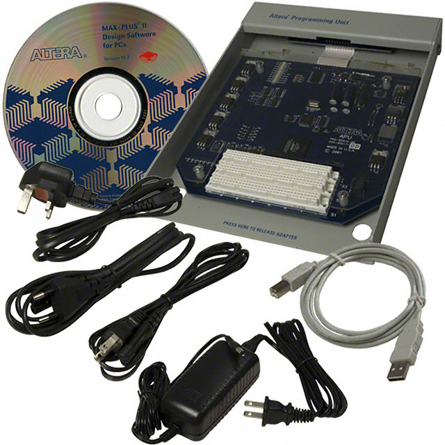
- Mark as New
- Bookmark
- Subscribe
- Mute
- Subscribe to RSS Feed
- Permalink
- Report Inappropriate Content
I also posted some info and Images here on my website.
http://www.digital-circuitry.com/mylab_cpld_prog.htm (http://www.digital-circuitry.com/mylab_cpld_prog.htm) -Gerry- Mark as New
- Bookmark
- Subscribe
- Mute
- Subscribe to RSS Feed
- Permalink
- Report Inappropriate Content
I attached a 5Volt DC power supply with a 1amp current rating. I figured chances are it would not be a lower voltage rating than 5 Volts so I took a chance. Well the Adapters programming light was vary Dim so I moved it up to a 6 Volt DC and still it was quite Dim, so I then used a 7.5 Volt DC supply and it seems to be at the regular brightness as the PL-ASAP2 programmer. However the Software is failing to detect the installed adapters.
-Gerry- Mark as New
- Bookmark
- Subscribe
- Mute
- Subscribe to RSS Feed
- Permalink
- Report Inappropriate Content
So I'm wondering if it is a 9V DC or possibly even a 12Volt But I'm not at the point to want to try that yet so I think I'll try and find someone that has the APU programmer and ask them what their Power supply ratings indicate.
-Gerry- Mark as New
- Bookmark
- Subscribe
- Mute
- Subscribe to RSS Feed
- Permalink
- Report Inappropriate Content
I guess I could just continue and use the PL-ASAP2 model but then what would be the point in having this USB model. It would allow me to use it with a Laptop as a portable programmer.
-Gerry- Mark as New
- Bookmark
- Subscribe
- Mute
- Subscribe to RSS Feed
- Permalink
- Report Inappropriate Content
Can you open the programmer and look for a power regulator chip near the power connector?
- Mark as New
- Bookmark
- Subscribe
- Mute
- Subscribe to RSS Feed
- Permalink
- Report Inappropriate Content
I took some HI-Resolution pictures of the Altera APU main PCB.
I did see some Voltage regulator components but I'm not sure how that determines the Proper input voltage. There are possibly several other circuits that do not use a voltage regulator and are connected to the same power supply input. Couldn't this potentially damage the circuits? I just wish Altera had it indicated the Voltage and current requirements in the User's manual. Such a pain in the Butt!! Regardless, Here are the Image links below: http://www.digital-circuitry.com/images/webpage/mylab/altera_apu_00b_%20012.jpg (http://www.digital-circuitry.com/images/webpage/mylab/altera_apu_00b_%20012.jpg) http://www.digital-circuitry.com/images/webpage/mylab/altera_apu_00b_%20014.jpg (http://www.digital-circuitry.com/images/webpage/mylab/altera_apu_00b_%20014.jpg) http://www.digital-circuitry.com/images/webpage/mylab/altera_apu_00b_%20015.jpg (http://www.digital-circuitry.com/images/webpage/mylab/altera_apu_00b_%20015.jpg) I also checked the underside of the PCB but there was no written text to indicate a voltage of any kind. If you can see anything on the TOP side of the APU PCB that may indicate a specific DC Input voltage please let me know. It would be greatly appreciated. Regards, Gerry O'Brien
- Mark as New
- Bookmark
- Subscribe
- Mute
- Subscribe to RSS Feed
- Permalink
- Report Inappropriate Content
There were no components at all near the DC input Jack. Only a small PCB with the rear connectors attached.
Then there is a small ribbon cable that connects this small connector PCB to the Main APU PCB. Which you can see in the image links I posted above. -Gerry- Mark as New
- Bookmark
- Subscribe
- Mute
- Subscribe to RSS Feed
- Permalink
- Report Inappropriate Content
I've tried to send a service request directly to Altera but they will not help with any information whatsoever because the unit is discontinued. I even tried emailing one of the provided email addresses on the "contact"section of the Altera website, asking them to divert my "email question" to Tech support. They just told me to submit my questions to the http://mysupport.altera.com link, which I already tried and they just ignored the email.
So It's up to you Altera Guru's to help me solve this problem. I really hope we can sort this out. Let me know if you can figure anything out. Thanks -Gerry- Mark as New
- Bookmark
- Subscribe
- Mute
- Subscribe to RSS Feed
- Permalink
- Report Inappropriate Content
What I would do is to gradually increase the DC voltage input and monitor all the LM317 regulators. IIRC the voltage adjustment pin should be at 1.25V. Increase the input voltage until all the LM317 have the correct adjustment voltages, and then measure all their output voltages. Using the highest regulated voltage and the minimum dropout requirement from the LM317 datasheet you'll know the minimum input DC supply voltage. I don't think that anything sensitive is directly running an the DC input supply.
- Mark as New
- Bookmark
- Subscribe
- Mute
- Subscribe to RSS Feed
- Permalink
- Report Inappropriate Content
Hi Daixiwen,
Thank you very much for that Tip. I managed to adjust the voltage and got the APU programmer running perfectly at 7.5 Volts DC (1.0 Amps) center positive. I had used this setting early on during testing which failed. It turns out that the power supply I was using at that time was damaged and it was only providing around 400mA or current. So now with the 1000mA supply, the APU-USB drivers detected the APU hardware perfectly and was able to properly install. I made this diagram for my archive. http://www.digital-circuitry.com/images/webpage/mylab/apu_power_connector_001.jpg (http://www.digital-circuitry.com/images/webpage/mylab/apu_power_connector_001.jpg) Thanks very much for all the help. Kind Regards, Gerry O'Brien
- Mark as New
- Bookmark
- Subscribe
- Mute
- Subscribe to RSS Feed
- Permalink
- Report Inappropriate Content
Gerry: in case you are still looking for the power supply info:
My factory supplied source is made by CUI Inc, Switching Mode Power Supply. Model EPA-151DA-09, P/N DTS090166UDC-PS-SZ. It is 9VDC 1.66A, center power pin.- Mark as New
- Bookmark
- Subscribe
- Mute
- Subscribe to RSS Feed
- Permalink
- Report Inappropriate Content
Hi jwiatrowski,
That's fantastic!! Thanks very much. Now I know I won't blow out any of the voltage regulators. :) I'll update my webpage. Thanks again. Kind Regards, Gerry O'Brien- Mark as New
- Bookmark
- Subscribe
- Mute
- Subscribe to RSS Feed
- Permalink
- Report Inappropriate Content
Just posting a few Images of the PL-APU power supply issued by Altera.
https://www.alteraforum.com/forum/attachment.php?attachmentid=8929 https://www.alteraforum.com/forum/attachment.php?attachmentid=8927 https://www.alteraforum.com/forum/attachment.php?attachmentid=8928 Cheers! -Gerry- Subscribe to RSS Feed
- Mark Topic as New
- Mark Topic as Read
- Float this Topic for Current User
- Bookmark
- Subscribe
- Printer Friendly Page