- Mark as New
- Bookmark
- Subscribe
- Mute
- Subscribe to RSS Feed
- Permalink
- Report Inappropriate Content
Hi..i am having a problem and don't have any idea how to solve this problem. I had do the simulation using modesim and working fine. However when I download the code to DE2 board with Cyclone II, the waveform observed from GPIO_0[0] have too much jitter (and other things and make the output waveform unusable).
What I am trying to do is to make a pulse generator where the pulse width and frequency can be adjusted. The pulse width is 2ns to 250ns and frequency from 1kHz to 2MHz. Anybody have any advise(s) on the codes (refer to attach file) ?Link Copied
- Mark as New
- Bookmark
- Subscribe
- Mute
- Subscribe to RSS Feed
- Permalink
- Report Inappropriate Content
You didn't post all design files, Ton_Ctrl.v is missing. I looked at sync_ctrl and trig_ctrl units and see that you misunderstand both the Verilog syntax for clocksensitive circuits and the hardware features of FPGA.
A flip-flop like pulse_out1 can have only one clock input. In the below shown always block from sync_ctrl.v, no clock is defined at all.always @(posedge mclk_in or posedge pclk_in or posedge clk180_in or posedge clk270_in or negedge rst_in)
begin
if (rst_in == 0)
pulse_out1 <= 1'b0;
else if (mclk_in)
begin
if ((trig_in)&&(pw_in) == 1)
pulse_out1 <= 1'b1;
else
pulse_out1 <= 1'b0;
end
else if (pclk_in)
begin
if ((trig_in)&&(pw_in) == 1)
pulse_out1 <= 1'b1;
else
pulse_out1 <= 1'b0;
end
else if (clk180_in)
begin
if ((trig_in)&&(pw_in) == 1)
pulse_out1 <= 1'b1;
else
pulse_out1 <= 1'b0;
end
else if (clk270_in)
begin
if ((trig_in)&&(pw_in) == 1)
pulse_out1 <= 1'b1;
else
pulse_out1 <= 1'b0;
end
else
pulse_out1 <= 1'b0;
end
- Mark as New
- Bookmark
- Subscribe
- Mute
- Subscribe to RSS Feed
- Permalink
- Report Inappropriate Content
- Mark as New
- Bookmark
- Subscribe
- Mute
- Subscribe to RSS Feed
- Permalink
- Report Inappropriate Content
What's the point of using 4 clocks instead of a single one with a 4-state process?
Besides the fact this is not synthetizable in fpga (as Fvm already said, a physical flip-flop has a SINGLE clock input), the overall logic flow of your code is wrong, too. For example, when you have a clk180_in clock edge, I believe you want the code inside "if (clk180_in)" to be executed; but, if mclk_in or pclk_in signal is still high this is not the case, since one of the previous "if" condition is also true.- Mark as New
- Bookmark
- Subscribe
- Mute
- Subscribe to RSS Feed
- Permalink
- Report Inappropriate Content
You should look at your design from a hardware viewpoint. A Verilog or VHDL is synthesizable, if it can be mapped to FPGA harware, particularly logic elements. You'll notice that the FPGA registers have only one clock input, you can't control a register by multiple clocks at the same time.
I understand that you need multiple phase shifted clocks to achieve the intended timing resolution, but it's impossible to output the fast output waveforms or internal signals from a single register. So as a first step you need to sketch a hardware circuit that is able to generate the intended waveforms. Combining multiple register outputs with combinational circuits can be a solution, that's also what the dedicated DDR output registers in Cyclone II and other FPGA families do.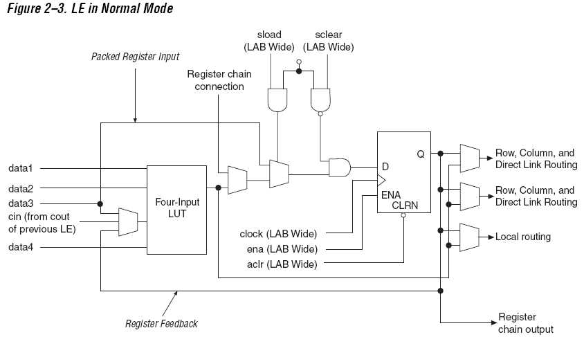
- Mark as New
- Bookmark
- Subscribe
- Mute
- Subscribe to RSS Feed
- Permalink
- Report Inappropriate Content
--- Quote Start --- What's the point of using 4 clocks instead of a single one with a 4-state process? Besides the fact this is not synthetizable in fpga (as Fvm already said, a physical flip-flop has a SINGLE clock input), the overall logic flow of your code is wrong, too. For example, when you have a clk180_in clock edge, I believe you want the code inside "if (clk180_in)" to be executed; but, if mclk_in or pclk_in signal is still high this is not the case, since one of the previous "if" condition is also true. --- Quote End --- Hi Cris72, the reason I m using 4 clocks because I want to achieve 1ns counter resolution. Ok..i understand the problem now. Thanks for pointing that out.
- Mark as New
- Bookmark
- Subscribe
- Mute
- Subscribe to RSS Feed
- Permalink
- Report Inappropriate Content
Hi FvM...thanks for the advise ....I need to go back to square one again and re-analyse the whole thing of how to generate a narrow pulse.
Just for my curiosity, why modesim did not able to spot this major errors ? and still able to show the correct waveform under simulation ?- Mark as New
- Bookmark
- Subscribe
- Mute
- Subscribe to RSS Feed
- Permalink
- Report Inappropriate Content
Your code may not involve syntax errors in terms of Verilog language rules. Verilog (or VHDL) aren't restricted to describe circuits synthesizable in actual hardware. It's your job to use only sysnthesizable constructs.
As I said, I thinks it's not primarly a Verilog problem. The problem is about understanding logic hardware design. Of course there's another point of using the right syntax for synthesizable Verilog. You'll find it e.g. in the Quartus Verilog templates.- Subscribe to RSS Feed
- Mark Topic as New
- Mark Topic as Read
- Float this Topic for Current User
- Bookmark
- Subscribe
- Printer Friendly Page