- Mark as New
- Bookmark
- Subscribe
- Mute
- Subscribe to RSS Feed
- Permalink
- Report Inappropriate Content
Hi,
I've written based on an Altera Example an IP of PLL and a SM which activates this. I've created on the PLL 25M and 100M clocks. However, I do not get any response - the clocks do not shift. Could you please advise ? // To control the phase shift SM - to toggle the phase shift back to '1' after shift always @ (posedge clock10m or negedge reset_n or posedge sequence_done) //or posedge i2c_wr_valid_s) if (~reset_n) toggle_phase_shift <= 1'b1; //set phase shift to '1' - phase shift SM in "reset" else if (sequence_done == 1) toggle_phase_shift <= 1'b0; //set phase shift to '1' - phase shift SM in "reset" else toggle_phase_shift <= (i2c_wr_valid_s & i2c_reg_addr == 32'h34) ? 1'b0 : toggle_phase_shift; PHASE_PLL_100M_To_25M dram_core_pll ( .areset (!reset_n ), //input, global reset .inclk0 (clock66m ), //input clock 66.666MHz .c0 (FP_PLL1_100M_CK_P), //output clock 100MHz synced to 66.666MHz .c1 (FP_PLL2_25M_CK_P), //output clock 25MHz synced to 66.666MHz .phaseupdown (phase_updown), .phasecounterselect (phase_clkslct), .phasestep (phase_en_wire), .phasedone (phase_done_wire), .scanclk (clock10m) ); SHIFT_PLL_SM shift_pll_sm ( .clk (clock66m), //input clock 66.666MHz .reset (toggle_phase_shift), //'0' starts the SM, default is '1' .phase_en (phase_en_wire), //enable phase shift from SM to PLL .phase_done (phase_done_wire), //phase done signal from PLL to the SM at end of a phase shift .num_of_steps (num_of_steps), //num_of_steps of phase shifts .sequence_done (sequence_done) //as sequence_done goes to '1', "reset" should go to '1' to wait for next user toggle to '0' );Link Copied
1 Reply
- Mark as New
- Bookmark
- Subscribe
- Mute
- Subscribe to RSS Feed
- Permalink
- Report Inappropriate Content
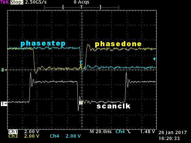
The dynamic phase shift capability isn't documented as clearly as it could be. I'm not sure how anyone has gotten it working by following the docs. I had to run the PHASESTEP, PHASEDONE, and SCANCLK signals out to a scope to see what was happening.
The timing diagram in the Cyclone IV device handbook (Oct 2012) looks like this: http://www.ke5fx.com/doc.png But what actually happens is that while PHASEDONE goes low on SCANCLK rising, it immediately goes high on the next falling edge: http://www.ke5fx.com/TDS_phaseadj.png As a result, you cannot build a state machine that watches for PHASEDONE falling ("Deassert PHASESTEP after PHASEDONE goes low") unless you drive it from the negative edge of SCANCLK. Synchronous logic on the positive edge of SCANCLK will never see PHASEDONE low unless it gets (temporarily) lucky with the timing. Or, it might be dependent on the relationship between the VCO and output clock in question, in which case it's a bug. So if you're still struggling with this, try the other clock edge.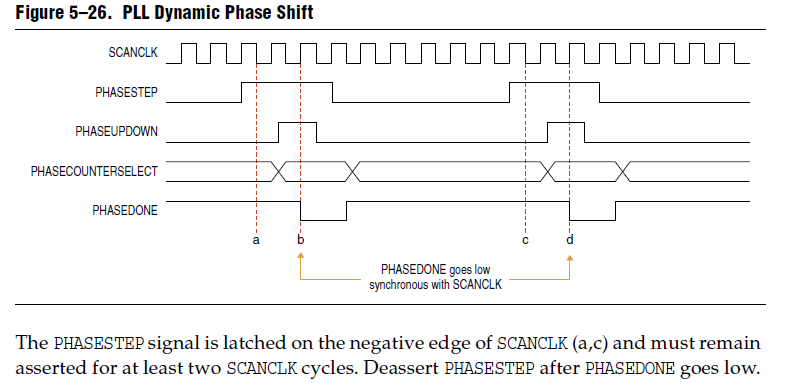
Reply
Topic Options
- Subscribe to RSS Feed
- Mark Topic as New
- Mark Topic as Read
- Float this Topic for Current User
- Bookmark
- Subscribe
- Printer Friendly Page