- Mark as New
- Bookmark
- Subscribe
- Mute
- Subscribe to RSS Feed
- Permalink
- Report Inappropriate Content
I can successfully perform an RSU using discrete logic implementation on a MAX10 device. I now want to confirm that the correct image has been loaded. My board has the CONFIG_SEL pin pulled up so it will always boot from the Update Image, unless something is wrong with it. I want to be use the Dual Boot IP core msm_cs value to read which image has been booted and have that be accessible to be read externally.
I am trying to simulate reading from the Dual boot IP in order to access offset 4 (specifically bits 16:13 for msm_cs but the whole register is fine) but the avalon readdata interface does not change in simulation.
The basic process for my reads are
1. Write 1'b1 to offset 2 bit 0 (due to the message above table table 34 in the MAX10 configuration User guide Page 62)
2. Wait for this write to finish (how long does this write take? I cannot find a value anywhere)
3. Read offset 3 bit 0 (busy register to make sure it is not busy) How long should I wait for reads?
4. Wait for avalon readdata[0] to be 0 (It always is, so this just moves on)
5. Read offset 4
6. Wait for Read to finish from offset 4
7. Assign the avalon readdata value to be brought out of my module
8. End
The value I get in sim for readdata is always 0, no matter how long I wait for operations to complete. Am I missing any steps or doing something wrong? The documentation seems to be fairly limited for this IP core. Is this even simulatable? I will try on HW and read with a UART but I don't expect it to work.
Link Copied
- Mark as New
- Bookmark
- Subscribe
- Mute
- Subscribe to RSS Feed
- Permalink
- Report Inappropriate Content
Based on my understanding, you are able to perform RSU with the Dual Configuration IP on MAX 10 in hardware but you are having issue in reading the offset 4 in simulation but not in hardware? May i know are you using modelsim simulation?
- Mark as New
- Bookmark
- Subscribe
- Mute
- Subscribe to RSS Feed
- Permalink
- Report Inappropriate Content
Yes that is correct. I have a requirement to confirm that the Update Image is booting, so I need to be able to tell using the Dual Boot IP core. Currently, my update build just has a different LED pattern, and when that file is downloaded via UART and power cycled, the update LED pattern appears. I just have the Dual Boot IP core instantiated currently, and not connected to anything, in order to compile.
Modelsim is what I am using but I have access to others.
Edit: Re-reading this, I cannot read anything in HW either. Any attempt to read from the Dual Boot IP in hardware or simulation does not work
- Mark as New
- Bookmark
- Subscribe
- Mute
- Subscribe to RSS Feed
- Permalink
- Report Inappropriate Content
Understand, wat about the other bit in offset 2? Have you tried to read them?
- Mark as New
- Bookmark
- Subscribe
- Mute
- Subscribe to RSS Feed
- Permalink
- Report Inappropriate Content
I have tried to write to offset 2 bit 3 and then do a read from offset 4 and still nothing.
The layout of the documentation isn't clear as to what register is the input register. I see two different sections in the MAX10 configuration user guide. I am reading table 34 for this but there is also tables 9-14 that also have information for the Dual Boot IP but I do not have any of those signals from the Dual Boot IP block that I instantiated.
- Mark as New
- Bookmark
- Subscribe
- Mute
- Subscribe to RSS Feed
- Permalink
- Report Inappropriate Content
Quick Update. I am now able to read from offset 4, after writing bit 0 of offset 2, but it always reads 0x00000001. This is the watchdog timer value, which I do not use or really care about.
- Mark as New
- Bookmark
- Subscribe
- Mute
- Subscribe to RSS Feed
- Permalink
- Report Inappropriate Content
Can you try to disable the watchdog timer and try again?
- Mark as New
- Bookmark
- Subscribe
- Mute
- Subscribe to RSS Feed
- Permalink
- Report Inappropriate Content
I do not see any register or setting that disables the watchdog timer. Table 34 on page 62 gives no option to disable the watchdog timer and those are the only signals I have access to.
I connected the Dual Boot IP core using platform designer and saw a sample of the read and write waveforms and I recreated exactly the timing for reads and writes but I still cannot read anything. Trying to match the example waveforms makes it worse. See attached pictures for the example, my writes and my reads
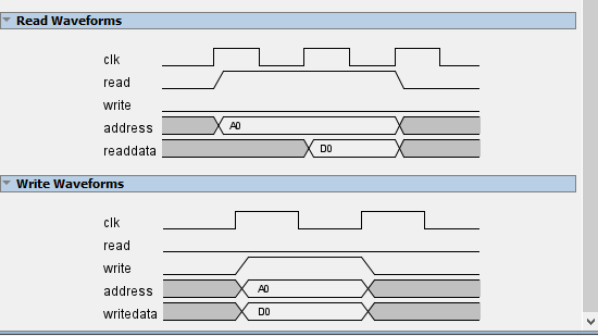
- Mark as New
- Bookmark
- Subscribe
- Mute
- Subscribe to RSS Feed
- Permalink
- Report Inappropriate Content
Another update, I now
1. write 1 to bit 0 of offset 2 and wait for this to happen (I think, there is no confirmation)
2. Read bit 0 of offset 3 and wait until this reads 0 (happens after ~150 clock cycles)
3. Read from offset 4. This now reads 0h0001FFFF. This is definitely better because I am pretty sure I am actually reading something, but bits [16:13] of this register are 1111 which does not correspond to an msm_cs value.
I am suspicious of the initial write since a previous forum post (https://community.intel.com/t5/Intel-FPGA-University-Program/MAX-10-FPGA-Remote-System-Upgrade-RSU/td-p/655190?profile.language=en) had this problem and it was fixed by writing to offset 2. I have tried waiting for over 531 clock cycles for this write to take place and have tried moving on right away like the avalon timing diagram mentioned above. Am I doing the writes wrong? Can this IP core even be simulated?
- Mark as New
- Bookmark
- Subscribe
- Mute
- Subscribe to RSS Feed
- Permalink
- Report Inappropriate Content
Hi,
Sorry for being late, it seems like this IP is not able to simulate. As per the thread you shared previously, customer is also seeing 1111 when there is no image loaded. Then, he / she sees 0010 when image 0 is loaded.
Can you try in hardware and see if it is working?
Thank You.
Regards,
Bruce
- Mark as New
- Bookmark
- Subscribe
- Mute
- Subscribe to RSS Feed
- Permalink
- Report Inappropriate Content
Hi, I turned to signal tap in order to debug this. I'm not really sure what I did/changed but I was able to see the correct values in signal tap depending on the image that was loaded.
I wish I could state what I was doing wrong, but the last thing I changed before it was working was specifying the address using bit notation instead of hex. (So 3'b001 instead of 3'h1). I'm not sure why this would break/fix anything but apparently it has.
- Mark as New
- Bookmark
- Subscribe
- Mute
- Subscribe to RSS Feed
- Permalink
- Report Inappropriate Content
Are you saying that you were using 3'h1 in Quartus Design and now changed to 3'b001 and it works now?
- Mark as New
- Bookmark
- Subscribe
- Mute
- Subscribe to RSS Feed
- Permalink
- Report Inappropriate Content
That was the last HDL change I made before it worked. I also added signal tap to look at the registers and saw it go from not working to working in signal tap. I made no other logic/state machine changes and it still does not work in simulation
- Mark as New
- Bookmark
- Subscribe
- Mute
- Subscribe to RSS Feed
- Permalink
- Report Inappropriate Content
I glad it works now. Help this can benefit other community. Cheers.
- Subscribe to RSS Feed
- Mark Topic as New
- Mark Topic as Read
- Float this Topic for Current User
- Bookmark
- Subscribe
- Printer Friendly Page