While doing gate-level simulation, i found an output miss-match in my design. I want to investigate it further but all the wire in module.vo files, that was previously assigned in module.v, was renamed. My design is quite big, I have to monitor around 4 1000-bit bus wires to investigate this error. Since the bus wires is vast, it is not possible to temporarily assign those wires as output wires. Are there any way to monitor 4 1000-bit bus wire in timing simulation? For more information, I use Quartus Prime 17.1.0 and ModelSim Intel FPGA 10.5b.
链接已复制
In a simulation, you don't have to bring out wires to top-level ports to monitor them. I forget the panel names in ModelSim, but once you've compiled the files in ModelSim, you can select a part of the design hierarchy in the sim Library and then in the object (?) window, you should see a list of all the signals in that part of the design. Just click and drag them over to the waveform window and then start the simulation.
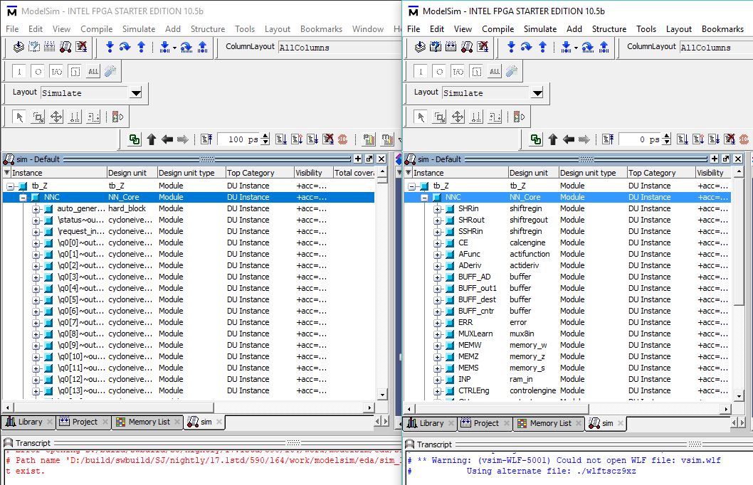
https://alteraforum.com/forum/attachment.php?attachmentid=14874&stc=1 i have post an image screen shot on https://ibb.co/dmxcax . Those images show the difference of wires inside the NNC module in different simulation setup, functional and timing, of the same testbench. The right hand side is functional simulation objects invoking module.v, the left hand side is timing simulation objects invoking module.vo. Those twos have totally different wires, or at least totally different name. For more information, those simulation generated by Quartus Prime nativelink. In case I had done wrong procedure, the process was simply full compilation (Ctrl-L) then click Tools>Run Simulation Tool>RTL Simulation or Tools>Run Simulation Tool>Gate Level Simulation. I follow this instruction https://www.altera.com/en_us/pdfs/literature/ug/ug_gs_msa_qii.pdf for EDA Tool Settings.
There's a separate window view in ModelSim I'm talking about where you drag and drop from. I wish I had the tool open right now, but I think it's the Object window (kind of a purple background). When you select one of the modules you list here, the Object window displays the signals in that module.
I am sorry for the messy reply before. I am new in this forum
Do you man this panel(attached)? If it is the right panel, I am still confused by the renaming problem. https://www.alteraforum.com/forum/attachment.php?attachmentid=14878
All my pre-assign wire was renamed in module.vo. The renaming pattern is in the chaotic way that i cant understand. Checking each wire new name is quite trouble some, the module.vo is around 3,000,000 lines. Furthermore complex wires such as sim:/tb_Z/NNC/CalcEng/b_bus[179:160] is not easy to trace
--- Quote Start --- I am sorry for the messy reply before. I am new in this forum Do you man this panel(attached)? If it is the right panel, I am still confused by the renaming problem. https://www.alteraforum.com/forum/attachment.php?attachmentid=14878 --- Quote End --- Yes, that's the panel I was referring to.