Hello,
I am working with Intel Max10 - 10M50DAF484C6GES for one of my applications, which has the requirement to transfer and receive the serial data (SERDES-LVDS) with data rate of 100Mbps. I am using individual IP Soft LVDS IP cores for TX and RX functionalities with 8 bit single channel and i am not using external PLL configurations. I am passing the parallel 8 bit data to TX_in from the testbech and passing the data to the RX_in through port mapping the TX_out pin from the test bench.
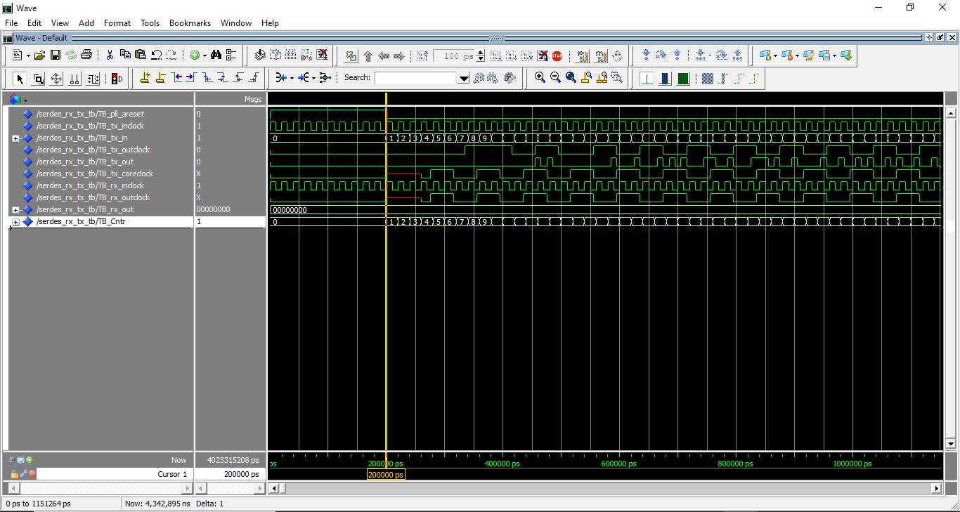
RX_out is "0" and not changing as wrt to input. I am attaching the waveform for the same with the test bench code. I am referring " MAX 10 High-Speed LVDS I/O User Guide", UG-M10LVDS
2015.05.04 document.
Can you please help me what changes has to be made for RX_out to change as per input.
The following is the configuration details of IP cores,
TX IP configurations:-
Power supply mode: Dual supply
Functional Mode: TX
Number of channels: 1
SERDES Factor : 8
Datarate: 100 Mbps
Input clock frequency: 50
TX_outclock division factor :8
Rx IP configurations:-
Power supply mode: Dual supply
Functional Mode: RX
Number of channels: 1
SERDES Factor : 8
Datarate: 100 Mbps
Input clock frequency: 50 MHz
following is my Test bench code:
Library IEEE;
use IEEE.std_logic_1164.all;
use IEEE.std_logic_unsigned.all;
use IEEE.numeric_std.all;
entity SERDES_RX_TX_TB is
end entity SERDES_RX_TX_TB;
Architecture RTL_TB of SERDES_RX_TX_TB is
Component SERDES_RX_TX is
port (
Top_tx_inclock : in std_logic := '0'; -- tx_inclock.tx_inclock
Top_tx_outclock : out std_logic; -- tx_outclock.tx_outclock
Top_tx_coreclock : out std_logic; -- tx_coreclock.tx_coreclock
Top_pll_areset : in std_logic := '0'; -- pll_areset.pll_areset
Top_tx_in : in std_logic_vector(7 downto 0) := (others => '0'); -- tx_in.tx_in
Top_tx_out : out std_logic;
Top_rx_inclock : in std_logic := '0'; -- rx_inclock.rx_inclock
Top_rx_outclock : out std_logic; -- rx_outclock.rx_outclock
Top_rx_in : in std_logic := '0'; -- rx_in.rx_in
Top_rx_out : out std_logic_vector(7 downto 0)
);
end component SERDES_RX_TX;
signal TB_tx_inclock : std_logic := '0';
signal TB_tx_outclock : std_logic;
signal TB_tx_coreclock : std_logic;
signal TB_pll_areset : std_logic := '0';
signal TB_tx_in : std_logic_vector(7 downto 0) := (others => '0');
signal TB_tx_out : std_logic;
signal TB_rx_inclock : std_logic := '0';
signal TB_rx_outclock : std_logic;
signal TB_rx_in : std_logic := '0';
signal TB_rx_out : std_logic_vector(7 downto 0);
signal TB_rx_data_align : std_logic := '0';
signal TB_rx_data_align_reset : std_logic := '0';
signal TB_Cntr : std_logic_vector (7 downto 0) := (others => '0');
constant CLK_PERIOD : time := 20 ns;
--constant CLK_PERIOD_2 : time := 20 ns;
begin
UUT: component SERDES_RX_TX
port map (
TOP_tx_inclock => TB_tx_inclock,
TOP_tx_outclock => TB_tx_outclock,
Top_tx_coreclock => TB_tx_coreclock,
TOP_pll_areset => TB_pll_areset,
TOP_tx_in => TB_tx_in,
TOP_tx_out => TB_tx_out,
TOP_rx_inclock => TB_rx_inclock,
TOP_rx_outclock => TB_rx_outclock,
TOP_rx_in => TB_tx_out,--TB_rx_in,
TOP_rx_out => TB_rx_out
);
Reset_Gen: Process
begin
--wait for 100 ns;
TB_pll_areset <= '1';
wait for 200 ns;
TB_pll_areset <= '0';
wait;
end process;
Clk_Gen: Process
begin
TB_tx_inclock <= not TB_tx_inclock;
TB_rx_inclock <= not TB_rx_inclock;
wait for CLK_PERIOD / 2;
end process;
Data_feed: process (TB_tx_inclock)
begin
if TB_pll_areset = '1' then
TB_Cntr <= "00000000";
elsif TB_tx_inclock'event and TB_tx_inclock = '1' then
for i in 0 to 9 loop
TB_Cntr <= TB_Cntr + '1';
end loop;
end if;
end process;
TB_tx_in <= TB_Cntr;
end RTL_TB;
I have also attached the simulation waveform for the reference.
Thanks in advance.
連結已複製
Hi,
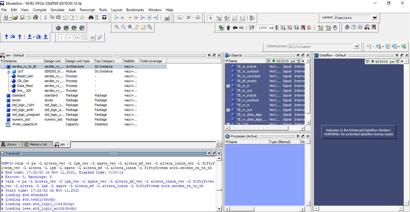
I am able to get the rx_out signal with your testbench and the settings that you mentioned.
Can you please try adding altera libraries during elaboration? You may use following command:
vsim -t ps -L altera_ver -L lpm_ver -L sgate_ver -L altera_mf_ver -L altera_lnsim_ver -L fiftyfivenm_ver -L altera -L lpm -L sgate -L altera_mf -L altera_lnsim -L fiftyfivenm work.serdes_rx_tx_tb
Regards
Hello,
Thank you for the reply. I tried with the command that you have provided in tcl command window, i am getting error . I have attached the screen shot for your reference "command.jpg". I could add the libraries using GUI, Assignments-> settings-> library (i have attached the screen shot for the same "library.jpg") but i see no change in the wave form, still RX_out stuck at "0".
Hi,
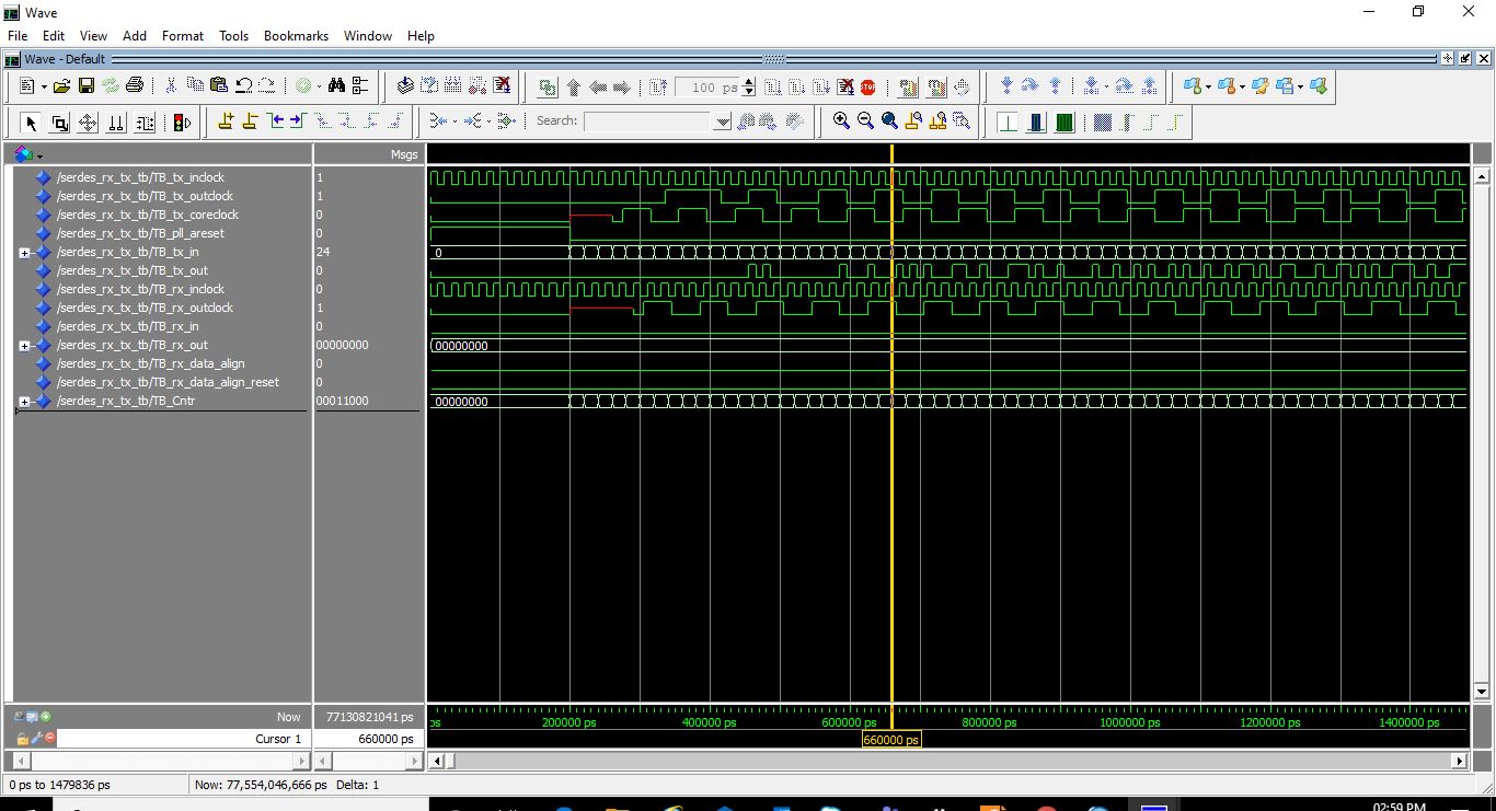
I tried adding the command that you given in model sim "waveform_command.jpg", no changes in the output wave from. Still RX_out is stuck at "0". I have attached the waveform for your reference "waveform_command.jpg".
Hi,
I tried inverting Rx_In_Clock, but no changes in the RX_out signal. Attached waveform for the reference.
Regards,
AK
Hi,
I tired inverting the rx_in clock, still the rx_out signal is stuck at '0'. Any further suggestions?
If you have any reference design, can you please share the link.
Regards,
This thread will be transitioned to community support. If you have a new question, feel free to open a new thread to get the support from Intel experts. Otherwise, the community users will continue to help you on this thread. Thank you