- Mark as New
- Bookmark
- Subscribe
- Mute
- Subscribe to RSS Feed
- Permalink
- Report Inappropriate Content
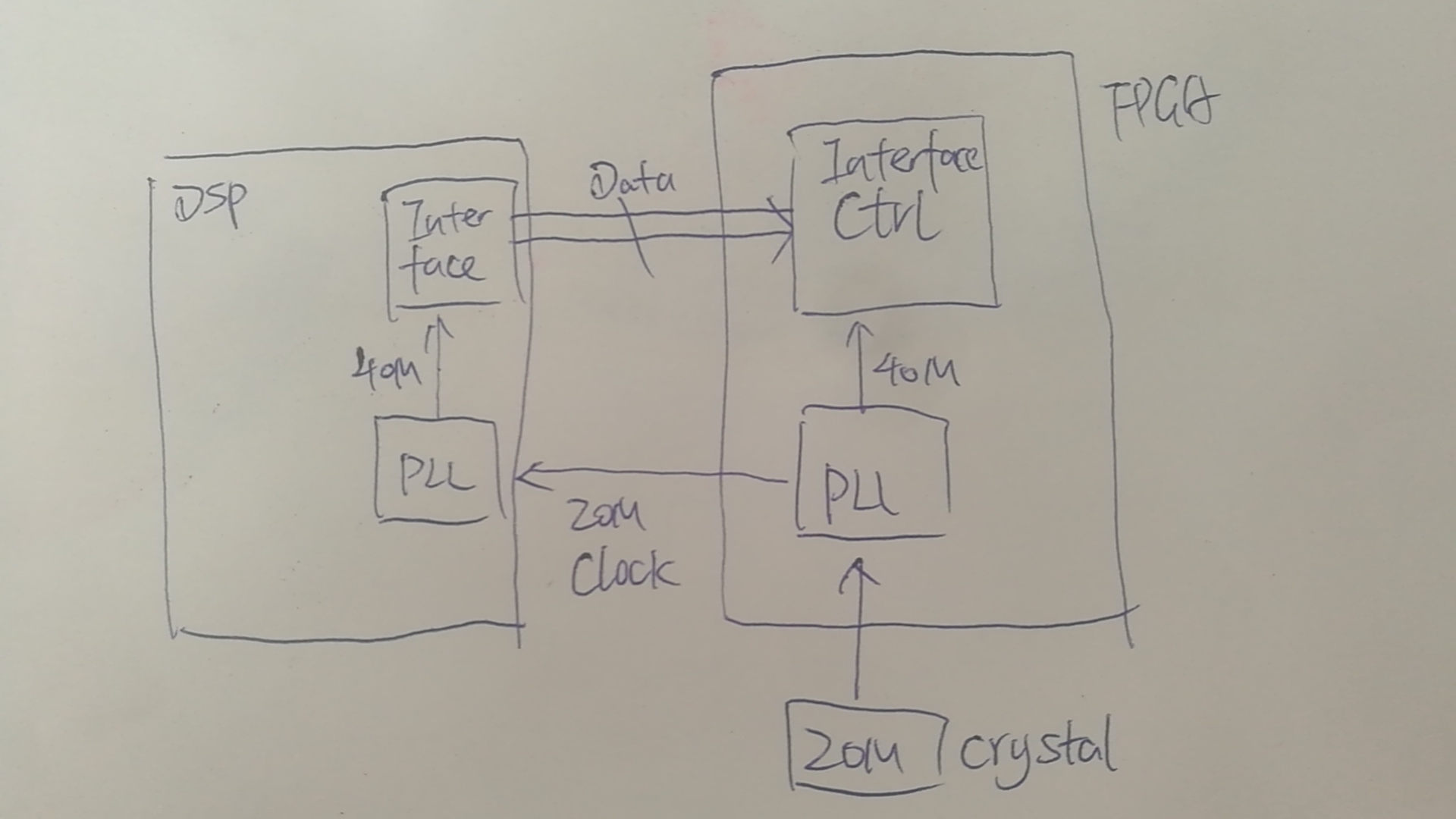
I'm using MAX10 to interface with a DSP. The FPGA is the clock provider whose PLL generated a 20Mhz clock to DSP and a 40Mhz clock(fpga_clk) for local use. The DSP uses DSP PLL to generated a 40Mhz local clock(dsp_clk) from the FPGA provided 20Mhz. Then the DSP uses this 40Mhz local clock(dsp_clk) to send parallel data/address to FPGA.
Since FPGA and DSP use different PLL to generate their own 40Mhz clock, so my question is can FPGA use its local 40Mhz clock(fpga_clk) to directly fetch data from DSP generated with dsp_clk? Is there any cross clock domain process needed? If it's not needed, how would the timing constraints be set in this scenario?
The timing parameter provided by the DSP datasheet includes the PLL input clock to output clock delay min/max value, the clock to output data delay.
Link Copied
- Mark as New
- Bookmark
- Subscribe
- Mute
- Subscribe to RSS Feed
- Permalink
- Report Inappropriate Content
Hi Ross Lee
You can refer to doc below as a starting point to understand how to manage metastability using Quartus Prime tools:
https://www.intel.com/content/dam/www/programmable/us/en/pdfs/literature/hb/qts/qts_qii51018.pdf
Thanks.
Eng Wei
- Mark as New
- Bookmark
- Subscribe
- Mute
- Subscribe to RSS Feed
- Permalink
- Report Inappropriate Content
Based strictly on your white board picture, the constraints you would need are:
1) base clock for the incoming 20 MHz clock from the crystal (create_clock)
2) generated clocks from the PLL (derive_pll_clocks)
3) additional generated clock for the output clock you're sending to the DSP (create_generated_clock -source <PLL output pin> -multiply_by 1 <target output port>
4) false path the clock output path so it's not analyzed as a data path (set_false_path)
The trickiest part I see is that the 40 MHz clock used by the DSP is based on the 20 MHz clock you're outputting. Normally in a data feedback design like this, the FPGA output clock would clock the data on the external device directly. So as you suggest, I'd change that 20 MHz output clock to a 40 MHz output clock to simplify things if you can. How does this external device's PLL work? Can you just feed a 40 MHz clock through it without any changes? Then the last constraints you'd need:
5) set_input_delay -max and -min with the reference clock as the output generated clock (#3 above) and the calculated values based on the full data arrival path (clock path delay from FPGA, external device tco, and data trace delay)
6(?) Not sure if that "interface ctrl" is outputting from the FPGA but if it is you'd need set_output_delay -max and -min as well
- Mark as New
- Bookmark
- Subscribe
- Mute
- Subscribe to RSS Feed
- Permalink
- Report Inappropriate Content
Hi Sstrell,
Thanks for your replying. I'd like to provide more details for your reference.
4) false path the clock output path so it's not analyzed as a data path (set_false_path)
...How does this external device's PLL work? Can you just feed a 40 MHz clock through it without any changes?
-- This DSP PLL is embedded in the DSP which can generate a local clock by multiplying the input reference clock. The original intention I used this PLL to generate 40Mhz from 20Mhz is to reduce the PCB layout timing restriction. Since 40Mhz would be easier for FPGA timing constraints as you suggested, I would try to use the 40Mhz clock between DSP and FPGA instead.
6(?) Not sure if that "interface ctrl" is outputting from the FPGA but if it is you'd need set_output_delay -max and -min as well
-- Sorry that I haven't made it clear. The depicted Databus between Interface module in DSP and Interface ctrl module in FPGA includes a 16bit data bus and some other control signals to each direction, like R/W, cs, and ready, so I reckon the set_output_delay max/min constraints are also needed.
- Mark as New
- Bookmark
- Subscribe
- Mute
- Subscribe to RSS Feed
- Permalink
- Report Inappropriate Content
Hi guys
since this thread has no more pending activity, I will transition this thread to community support. If you have a new question, feel free to open a new thread to get the support from Intel experts. Otherwise, the community users will continue to help you on this thread. Thank you.
- Subscribe to RSS Feed
- Mark Topic as New
- Mark Topic as Read
- Float this Topic for Current User
- Bookmark
- Subscribe
- Printer Friendly Page