- Mark as New
- Bookmark
- Subscribe
- Mute
- Subscribe to RSS Feed
- Permalink
- Report Inappropriate Content
Hello,
i'm trying to test my MAX10 using clock of 1MHz on some pins. one of the HW pins is not output the signal as expected, the clock goes high to 3.3v and then down to 1.6v instead of 0v. the pin location is PIN_119 and its configurations in the assignment editor are: 1. Location - PIN_119 2. I/O Standard - 3.3-v LVCMOS 3. Current Strength - Maximum Current 4. PCI I/O - On the specific pin is a DIFFIO_RX_T30p but i think the second configuration should set this pin as I/O output instead of differential pin. have i missing something? or the pin is damaged? thanks.Link Copied
8 Replies
- Mark as New
- Bookmark
- Subscribe
- Mute
- Subscribe to RSS Feed
- Permalink
- Report Inappropriate Content
What else is connected to this pin - what's loading it?
Everything you've stated looks fine. Given you're using 3.3V LVCMOS, you can ignore the DIFFIO function of the pin. Cheers, Alex- Mark as New
- Bookmark
- Subscribe
- Mute
- Subscribe to RSS Feed
- Permalink
- Report Inappropriate Content
nothing loading the pin.
it connected directly to the scope using a standard probe.- Mark as New
- Bookmark
- Subscribe
- Mute
- Subscribe to RSS Feed
- Permalink
- Report Inappropriate Content
Then you either have a fault on your board, you're probing badly or you've not written the code correctly. Consider posting some code, or the project, here.
Is your oscilloscope set to DC coupled? AC coupled would give funny results, although not those you describe. Cheers, Alex- Mark as New
- Bookmark
- Subscribe
- Mute
- Subscribe to RSS Feed
- Permalink
- Report Inappropriate Content
this could happen from bad verilog coding?
as far as i know digital output can't be biased. its output only logic levels 0v and Vdd. on the board there is nothing connected between the HW pin and the scope probe. in addition, if i probing other HW pins that wired with the same digital signal (1MHz clock) i see the expected clock on the scope screen, rail to rail. the print screen of the signal from the biased HW pin is attached. so my conclusion is my test setup from the probe perspective is ok. which else configuration parameters in the quartus project should i check?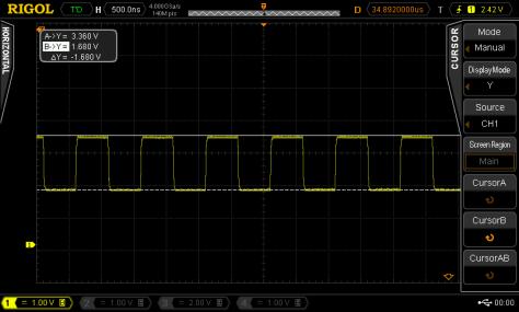
- Mark as New
- Bookmark
- Subscribe
- Mute
- Subscribe to RSS Feed
- Permalink
- Report Inappropriate Content
Then I fear you have a device fault on that pin. Try driving that pin permanently to GND from your code.
Cheers, Alex- Mark as New
- Bookmark
- Subscribe
- Mute
- Subscribe to RSS Feed
- Permalink
- Report Inappropriate Content
I have a similar issue.. I am creating a 150MHz clock from the internal PLL using using a 25MHz external clock.
I changed the clock assignment to 100Mhz and the output looks great. I am using 10M02SCE144C8G My 25MHZ clock is applied to pin 27 My 150MHZ clock comes out on pin 141, I have a TP at pin 31, where I send a copy of the signal. On pin 141 I have a series termination resistor. which I have lifted one side... Not understanding why the frequency is ok but voltage levels are off.. my PLL outputs are: C0 100MHZ internal C1 100MHz external C2 150MHz external C3 FPGA_PIN31 Any help would be great..- Mark as New
- Bookmark
- Subscribe
- Mute
- Subscribe to RSS Feed
- Permalink
- Report Inappropriate Content
How good is your oscilloscope? Or, more importantly, your scope probe. What bandwidth do they have and what loading is your probe adding to your circuit?
If the bandwidth is not 'enough', or the probes load too high, it's going to result in a very good looking waveform with reduced amplitude. To look at a 150MHz clock with any confidence I'd suggest you need at least 1GHz bandwidth on scope and probe. Cheers, Alex- Mark as New
- Bookmark
- Subscribe
- Mute
- Subscribe to RSS Feed
- Permalink
- Report Inappropriate Content
--- Quote Start --- How good is your oscilloscope? Or, more importantly, your scope probe. What bandwidth do they have and what loading is your probe adding to your circuit? If the bandwidth is not 'enough', or the probes load too high, it's going to result in a very good looking waveform with reduced amplitude. To look at a 150MHz clock with any confidence I'd suggest you need at least 1GHz bandwidth on scope and probe. Cheers, Alex --- Quote End --- Thanks for the suggestion... That was it...go to a faster Oscope...
Reply
Topic Options
- Subscribe to RSS Feed
- Mark Topic as New
- Mark Topic as Read
- Float this Topic for Current User
- Bookmark
- Subscribe
- Printer Friendly Page