- Mark as New
- Bookmark
- Subscribe
- Mute
- Subscribe to RSS Feed
- Permalink
- Report Inappropriate Content
Hi,
on a custom board we have successfully used an altera Cyclone V (5CEBA2) with an EPCQ32 (ASx4). Now we had to migrate from the EPCQ32 to the EPCQ32A. We used Quartus Prime Lite 17.1.0 and 17.1.1 and programmed the EPCQ32A via the Quartus Programmer + USB blaster + SFL. We followed the migration guideline AN822: https://www.altera.com/documentation/tfb1498107381358.html (https://www.altera.com/documentation/tfb1498107381358.html) After updating the EPCQ in Quartus from EPCQ32 to EPCQ32A, compilation and download of the .jic file to the EPCQ32A are successful, but then the FPGA fails to load the configuration file at startup (CONF_DONE remains low). We believe the hardware is fine (never had a problem with the EPCQ32). (MSEL: 10011, nCE to GND, nSTATUS, nCONFIG, CONF_DONE with 10k pull-up to 3V3, six lines between the EPCQ32A and the FPGA (DATA[3..0], nCS, DCLK) What we noticed in the map file is the following line: quad-serial configuration device dummy clock cycle: 12
whereas the AN822 states: --- Quote Start --- epcq—the dummy clock is configurable with the non-volatile configuration register (nvcr). when the epcq is used with a cyclone® v, arria® v or stratix® v device, the dummy clock is configured to be 4, 10 or 12, depending on the byte-addressing mode and asx1 or asx4 configuration. however, in epcq-a devices, the dummy clock is fixed at 8 and 6 for fast read and extended quad input fast read respectively. therefore you must regenerate the programming files, such as .pof, .jic, and .rpd.
--- Quote End --- Is the dummy clock cycle wrong and is it the cause of our problem? If this is our problem, how can we fix it? (we did not find any place where the dummy clock can be adjusted) Or is the problem somewhere else? What else can we check? Thanks for your help, Regards
Link Copied
- Mark as New
- Bookmark
- Subscribe
- Mute
- Subscribe to RSS Feed
- Permalink
- Report Inappropriate Content
Some oscilloscope screenshots that may help:
Screenshots taken at board power up, triggered on the first falling edge of nCS of the EPCQ devices (CH1 - top trace) Left-hand side: board with EPCQ32 (working well) Right-hand side: board with EPCQ32A (Configuration fails) Auto-restart configuration after error: enabled DCLK starts at 12.5 MHz. After some time DCLK goes to 100MHz, according to the "Active serial clock source: 100 MHz internal oscillator" setting. On the board with the EPCQ32 device, the configuration lasts for tens of milliseconds and is successful. On the board with the EPCQ32A, we counted approximately 1664 clock cycles @ 100 MHz; after that nCS goes hi and the configuration process is aborted. Setting the "Active serial clock source" to "12.5 MHz internal oscillator" does not change the behaviour: after the same number of clock cycles (approx. 1664) from where the clock frequency was supposed to change (in fact, with this setting it does not change), nCS goes hi and the configuration process is aborted in the same manner CH2: DCLK https://www.alteraforum.com/forum/attachment.php?attachmentid=15290 CH2: D0 https://www.alteraforum.com/forum/attachment.php?attachmentid=15292 CH2: D1 https://www.alteraforum.com/forum/attachment.php?attachmentid=15293 CH2: D2 https://www.alteraforum.com/forum/attachment.php?attachmentid=15294 CH2: D3 https://www.alteraforum.com/forum/attachment.php?attachmentid=15295- Mark as New
- Bookmark
- Subscribe
- Mute
- Subscribe to RSS Feed
- Permalink
- Report Inappropriate Content
Hi,
I would assume you should generate the *.pof from the *.sof as stated under "Programming File Regeneration Guideline". That should do the required changes as you select the target Config-EPROM.(https://www.altera.com/documentation/tfb1498107381358.html#bkz1500385055860__table_jng_n3d_bdb) KR, Carlhermann- Mark as New
- Bookmark
- Subscribe
- Mute
- Subscribe to RSS Feed
- Permalink
- Report Inappropriate Content
Hi Carlhermann,
Thanks for your help. We tried to follow your advice. What we found out is that: 1) the .pof file is automatically generated along with the .sof file during compilation 2) the .jic file is generated from the .sof file. As far as we know, there is no way to generate the .jic file starting from the .pof file 3) In the Quartus Programmer, we tried to program the EPCQ device using the .pof file, rather then the .jic file. When adding the .pof file an error message appears: "Cannot add target device EPCQ32A to device chain when in current programming mode" We followed the instructions given in "Programming File Regeneration Guideline" of AN822 with no success (BTW, the .pof file is not mentioned in that secion of the AN822).- Mark as New
- Bookmark
- Subscribe
- Mute
- Subscribe to RSS Feed
- Permalink
- Report Inappropriate Content
Hi,
the *.pof file is for programming the EPCQ by active Serial I/F only, as you use a *.jic I assume you only have the JTAG I/F on board. The *.jic is using the FPGA to Programm the EPCQ by first programming the FPGA with a internal programmer and then "shifting" the programming file into the EPCQ (which is the *.sof). As JTAG accepts only the *.sof, the *.jic can only be generated using the *.sof as the programming file. The "Cannot target device... when in current programming mode" relates to the programmer detecting the mismatch between configuration "JTAG mode" and programming file *.pof being for active Serial. Regenerating the *.pof thus only works, if you have active Serial I/F for programming on board. If you only have JTAG, the interesting question is, whether a *.jic File for the Cyclone II can be generated, including a version of the internal programmer capable to deal with the EPCQ-A EEPROM... Maybe this is a question Intel PSG Needs to answer... Can you raise a "MySupport" issue for this?- Mark as New
- Bookmark
- Subscribe
- Mute
- Subscribe to RSS Feed
- Permalink
- Report Inappropriate Content
Hi Carlhermann,
correct, we only have the JTAG interface on the board. The AS interface is between the FPGA and the EPCQ32A: there are no connectors or other devices connected to the AS interface, besides the EPCQ32A and the Cyclone V. We captured the signals nCS, DCLK, DATA0 and DATA1 at board power up. The FPGA sends the following Operation codes to the EPCQ32A memory: - 05h, read status. Reply: zero - 9Fh, read device identification: reply 16h, which is correct (EPCQ32 and EPCQ32A have the same ID according to their datasheets) - 0Bh, fast read (from address zero): the memory replies with some data - EBh, extended quad input fast read: the memory replies with some data, but then after approximately 220 bytes the FPGA raises nCS and the operation is aborted. (with the EPCQ32, this last operation lasts until all configuration data is transferred from the memory to the FPGA) The last operation code is executed at the clock frequency set in Device Configuration in Quartus, whereas the previous operation codes are executed at 12.5 MHz (nominal). We already raised a "MySupport" issue for our original problem (i.e. the FPGA cannot load the configuration data from the EPCQ32A). We are currently awaiting a reply. Thanks, Regards.- Mark as New
- Bookmark
- Subscribe
- Mute
- Subscribe to RSS Feed
- Permalink
- Report Inappropriate Content
Dear all,
on the very same board we tested an EPCQ32 and an EPCQ32A. Both can be successfully programmed through JTAG (Quartus Programmer (.jic) + USB Blaster + factory default enhanced SFL image + Active Serial), but configuration of the Cyclone V from the EPCQ32A fails during the "extended quad input fast read". Test setup: - Quartus 18.0 - blinking LED project without any IPs - project compiled and .jic generated for the EPCQ32 and for the EPCQ32A, following AN822 No useful help from Intel PSG after several days. This problem is delaying our production! We do not have to use an EPCQ flash, but we can use any compatible ASx1 or ASx4 NOR flash. Does anyone know an alternative, non-obsolete flash (can be larger than 32Mbit) that can be used in place of the Intel EPCQ? Thanks, Best regards,- Mark as New
- Bookmark
- Subscribe
- Mute
- Subscribe to RSS Feed
- Permalink
- Report Inappropriate Content
Hi,
well based on my experience, this behaviour points to the FPGA not identifying the configuration data as valid. Just as an example if you programm some file to the EEPROM containing data for other chip as the one on board (e.g. file for EP4CE15 and EP4CE22 installed). s My only "workaround" to get the production running again would be to try either setting up a board with active serial interface to the EEPROM (or modifying one board to get Access to the active Serial I/F) and check if programming the EEPROM directly works. if so, this is no nice workaround to Programm the EEPROM before soldering, but it keeps you in production - if not the issue is definitely related to the configuration file rather the Programming via JTAG... Regards, Carlhermann- Mark as New
- Bookmark
- Subscribe
- Mute
- Subscribe to RSS Feed
- Permalink
- Report Inappropriate Content
Hi,
We are still investigating the issue. We found out that by touching pins D0 or D1 of the EPCQ32A device with an oscilloscope probe during the configuration phase, the FPGA immediately loads the configuration data and configuration is successful. This suggests that we are facing a signal integrity issue. Warm boards (and devices) work better than cold ones. Adding 10pF 0603 capacitors between each Dx signal and GND on the EPCQ32A pins seems to mitigate our issue (on most boards the FPGA loads the configuration data at the first attempt). However, we are yet to find a solution that works on any board and at any temperature (say -10 to 40°C). We do not have series resistors on D0-D3, nCS and DCLK between the EPCQ32A and the 5CEBA2F17C7N FPGA. We have a 6-layer board, ground plane with no interruptions. Track lengths (between flash and FPGA) are as follows: pin sig mm 1 nCS 17.9 2 D1 18.6 3 D2 22.9 4 GND 5 D0 14.3 6 CLK 15.4 7 D3 11.7 8 3V3 2 vias per signal. track widths: 8mil VCC (flash and FPGA I/O banks): 3V3 Please note that an EPCQ32 flash works while an EPCQ32A flash fails to configure the FPGA (on the very same board). Maybe the EPCQ32 has more relaxed rise/fall times than the EPCQ32A (the datasheets do not provide any data about the device's rise/fall times) Configuration clock frequency: does not have any impact. A view of the PCB is attached (D0-D4, nCS and DCLK are highlighted). Red: top Blue: bottom Brown: intermediate signal plane In our view, the tracks are relatively short and we would not have expected signal integrity issues, although this seems to be the case. Are there any guidelines for the PCB layout of the EPCQ-A memory signals? Do the EPCQ-A need a by-pass capacitor? We put a 100nF, 0603 between VCC and the ground plane, with very short tracks. Is 100nF enough? The EPCQ-A datasheet does not mention it, nor it provides PCB layout guidelines. Are series resistors recommended? Any advice? Thanks, Best regards, Matteo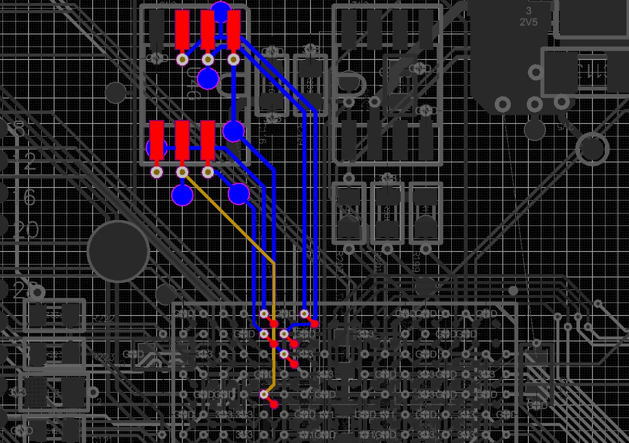
- Mark as New
- Bookmark
- Subscribe
- Mute
- Subscribe to RSS Feed
- Permalink
- Report Inappropriate Content
Hi,
I use an Arria V and replaced an EPCS128 with EPCQ128A - same issue: it programs/verifies fine via JTAG/.jic but configuration fails. I posted a thread yesterday but no response so far. So frustrating. And production is halted.- Mark as New
- Bookmark
- Subscribe
- Mute
- Subscribe to RSS Feed
- Permalink
- Report Inappropriate Content
Hi rbatfmi,
Out of 25 boards with the EPCQ32A , 4 works well (16%), configuration fails on the others. We used the SO8 package (AS x4). We soldered 0805 10pF C0G capacitors between pins 2, 3, 5 and GND (pin 4). i.e. between D0, D1, D2 and GND. After this modification, the configuration works on all boards (tested at room temperature, at approx. -10°C and at approx +50°C). We do not like this solution, but we could not find a better one. It is not clear to us what causes the problem and why these capacitors solve the problem. An hypothesis is that the EPCQ-A might have faster edges than the EPCQ devices and that the capacitors increase the rise/fall times. This, in turn, would improve the quality of the signals at the other end (the FPGA side) of the tracks. Other ideas? A reply with more details is currently awaiting approval (due to the attached files). I expect it to be published over the following days.- Mark as New
- Bookmark
- Subscribe
- Mute
- Subscribe to RSS Feed
- Permalink
- Report Inappropriate Content
Adding 33 Ohm 0805 resistors in series to each data line (between the flash pins and the corresponding pads on the PCB) solved our problem with the EPCQ32A.
On the same board the EPCQ32 works without those resistors. Thus, they are clearly not equivalent regarding the PCB design. The EPCQ-A devices are less forgiving.- Mark as New
- Bookmark
- Subscribe
- Mute
- Subscribe to RSS Feed
- Permalink
- Report Inappropriate Content
Hi everybody,
is there any new knowledge about this problem?
I testet Winbond W25Q128JVEIQ flashes and got the same problem. I soldered capacitors (10pf 0805) between the Data lines and ground, on some boards this solution work fine but not at all.
So i changed to Cypress S25FL128SAGNFI01 with this flash device all boards run without capacitors, but not stable.
Every 10 times the configuration fails.
Does anybody know a flash device with WSON-8 (8x6mm) package that runs reliable?
- Mark as New
- Bookmark
- Subscribe
- Mute
- Subscribe to RSS Feed
- Permalink
- Report Inappropriate Content
Has anyone tried going to AS1 instead of AS4? We have this issue right now. I changed to AS1 and 3 of the boards that would not configure are now working.
- Subscribe to RSS Feed
- Mark Topic as New
- Mark Topic as Read
- Float this Topic for Current User
- Bookmark
- Subscribe
- Printer Friendly Page