- Mark as New
- Bookmark
- Subscribe
- Mute
- Subscribe to RSS Feed
- Permalink
- Report Inappropriate Content
Hi,
I am using the Timing Analyzer of Quartus Prime 21-1 Pro.
I have to constrain a source synchronous interface and a questions arose while observing the setup timing report.
In my design (see attached screenshot) the output of my pll feeds:
. a FF, which data is then sent to an output port (LOSI.MOSI)
. an output port, used as clock for my synchronous interface (LOSI.CLK)
The timing constraints are:
. PLL clocks are generated automatically, therefore I do not write them explicitly (not even the base clock)
. I generate a clock from the PLL out
create_generated_clock -name LOSI_CLK_OUT \
  -source [get_pins {rcv_s10_top|sys_clk_rst|sw_pll|iopll_0|stratix10_altera_iopll_i|s10_iopll.fourteennm_pll|outclk[0]}] \
  [get_ports {losi.clk*}]
. I set an output delay based on that clock
set_output_delay -clock LOSI_CLK_OUT -max $my_delay [get_ports {losi.mosi*}]
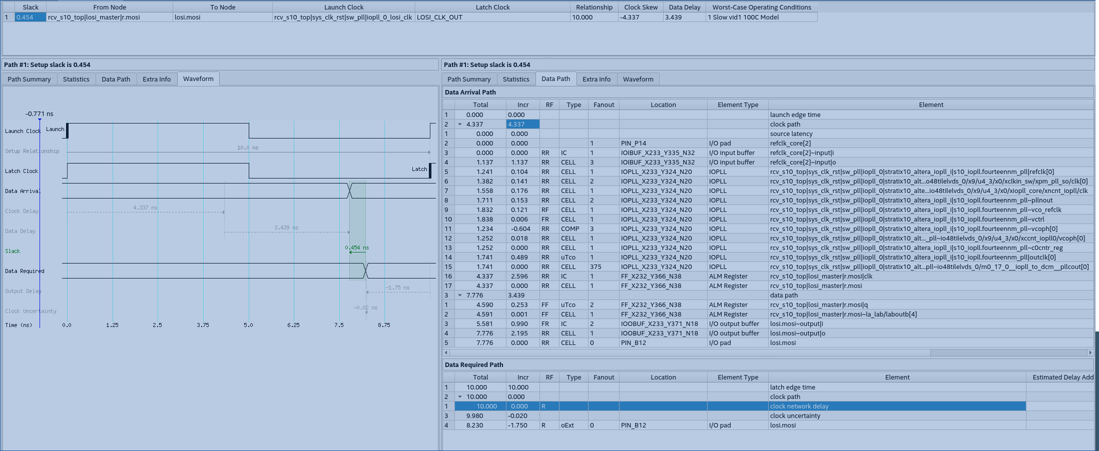
PROBLEM: When i check the setup relation on the MOSI pin, I do not see the clock network delay at the data required path.. that seems wrong!!
report_timing -to [get_ports {losi.mosi}] -setup -detail full_path
See the screenshot setup_timing.
I would have expected to see at least 4-5 ns of clock network delay, similar to the clock of the MOSI FF, but there is 0, as the clock was virtual and not generated.
Can anybody help?
Regards,
Rob.
UPDATE: the issue was solved and was due to a TCL variable set with the same name of the generated clock.
Link Copied
- Mark as New
- Bookmark
- Subscribe
- Mute
- Subscribe to RSS Feed
- Permalink
- Report Inappropriate Content
Hi,
I'm glad to hear that your problem is solved. Can you share your solution so that it may help others in the future?
Thanks and regards,
Nurina
- Mark as New
- Bookmark
- Subscribe
- Mute
- Subscribe to RSS Feed
- Permalink
- Report Inappropriate Content
The 'update' in the Post is wrong. I'd like to remove that line in the post but it seems not possible anymore.
The issue was solved not by reordering the TCL variables in my code but by changing the clock definition.
This is the erratic code:
create_generated_clock -name LOSI_CLK_OUT \
  -source [get_pins {rcv_s10_top|sys_clk_rst|sw_pll|iopll_0|stratix10_altera_iopll_i|s10_iopll.fourteennm_pll|outclk[0]}] \
  [get_ports {losi.clk*}]
As I am using differential inputs therefore i generated one single clock for both P and N input.
This has confused the Timing Analyzer leading to the wrong timing report attached.
The solution was to define a single clock at the P pin (see the attached screenshot):
create_generated_clock -name LOSI_CLK_OUT \
  -source [get_pins {rcv_s10_top|sys_clk_rst|sw_pll|iopll_0|stratix10_altera_iopll_i|s10_iopll.fourteennm_pll|outclk[0]}] \
  [get_ports {losi.clk}]
I am not fully sure if this is a bug or a known limitation in Timing Analyzer. If someone can confirm my finding I could consider opening a ticket (bug)
- Mark as New
- Bookmark
- Subscribe
- Mute
- Subscribe to RSS Feed
- Permalink
- Report Inappropriate Content
Hi,
It's possible that Timing Analyzer is ignoring the constraint. Could you Report Ignored Constraints and see which constraints are being ignored?
Additionally could you provide your .qar file of your project? To generate a .qar file, go to Projects>Archive Project
Regards,
Nurina
- Mark as New
- Bookmark
- Subscribe
- Mute
- Subscribe to RSS Feed
- Permalink
- Report Inappropriate Content
Hello,
We did not receive any response to the previous reply provided, thus I will put this case to close pending. Please post a response in the next 15 days to allow me to continue to support you. After 15 days, this thread will be transitioned to community support. The community users will be able to help you with your follow-up questions.
Regards,
Nurina
P/S: If you like my comment, feel free to give Kudos. If my comment solved your problem, feel free to accept my comment as solution!
- Subscribe to RSS Feed
- Mark Topic as New
- Mark Topic as Read
- Float this Topic for Current User
- Bookmark
- Subscribe
- Printer Friendly Page