- Mark as New
- Bookmark
- Subscribe
- Mute
- Subscribe to RSS Feed
- Permalink
- Report Inappropriate Content
I'm using Quartus 18.1 ,
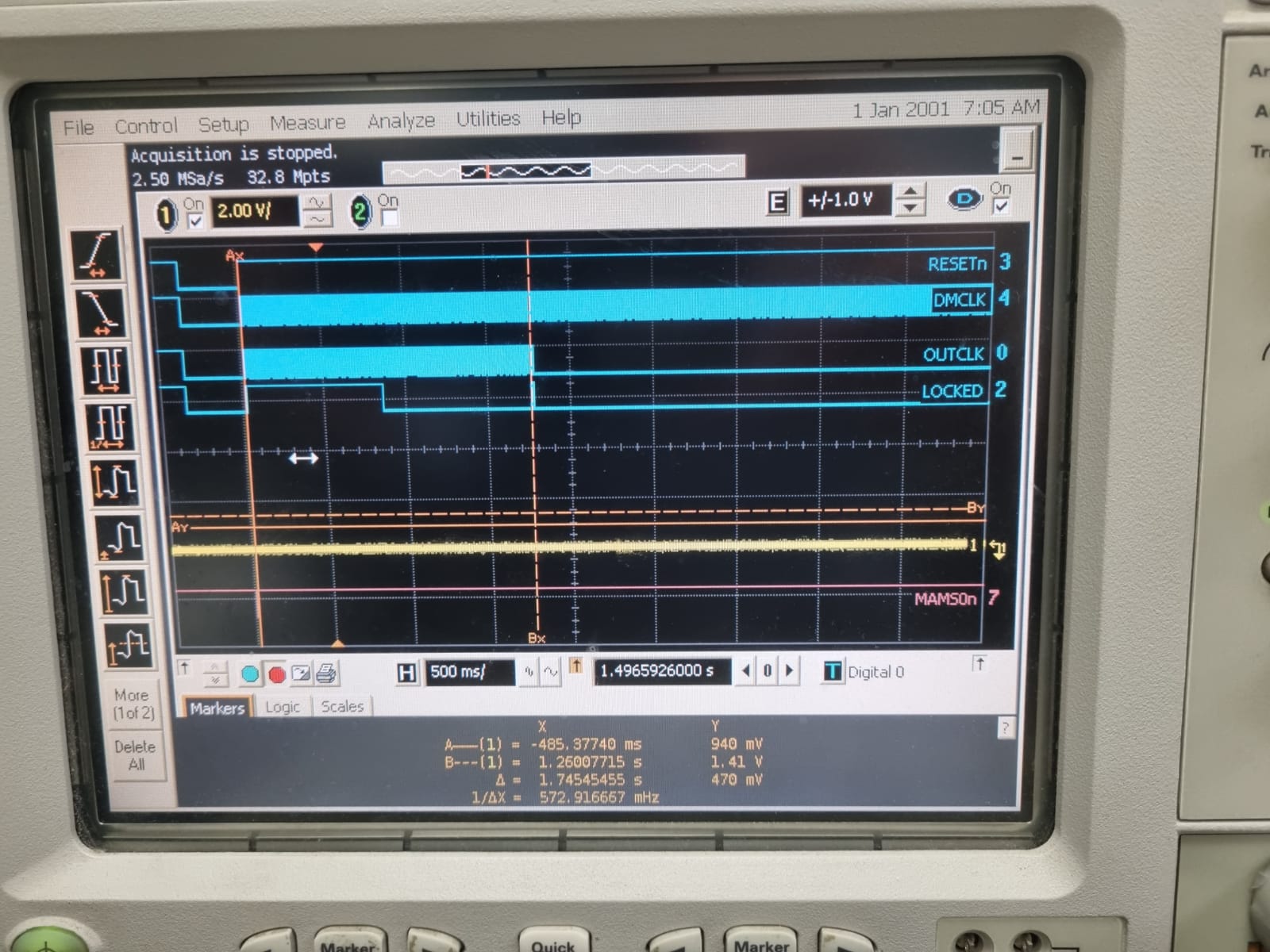
The source clock, output clock, reset signal and locked signal can be viewed on test pins (see attached scope capture).
All VCCA_FPLL pins are driven from a 2.5V source. and I check all the other voltage.
My board has 3 independent channels connected to the same host interface
Link Copied
- Mark as New
- Bookmark
- Subscribe
- Mute
- Subscribe to RSS Feed
- Permalink
- Report Inappropriate Content
Hi,
There could be many reasons for PLL to loose the lock. I recommend you to go through this checklist and try to find if everything is in place.
https://cdrdv2.intel.com/v1/dl/getContent/652735?explicitVersion=true&wapkw=pll%20lock%20checklist
Regards
- Mark as New
- Bookmark
- Subscribe
- Mute
- Subscribe to RSS Feed
- Permalink
- Report Inappropriate Content
Hello
I have revised my PCB and added a ground plane beneath the voltage regulator. However, I am still experiencing issues with the PLL not working on some channels. When measuring the voltage on the RREFֹTL pin, I am seeing 0V. I believe this may be indicative of a problem. What steps would you recommend I take to resolve this issue?
regards
- Subscribe to RSS Feed
- Mark Topic as New
- Mark Topic as Read
- Float this Topic for Current User
- Bookmark
- Subscribe
- Printer Friendly Page