- Mark as New
- Bookmark
- Subscribe
- Mute
- Subscribe to RSS Feed
- Permalink
- Report Inappropriate Content
Hi All,
I have attached a figure showing my filter issue. Please subtract 28 MHz from the x axis values (it was a typo). It is apparent that there is a strong DC peak in the plot. My question is how to reduce the DC to the noise level? This fft result is generated by the following process: Input signal: 28.05 MHz (generated from signal generator) Input sample rate: 160 MHz Output sample rate: 250 KHz NCO frequency: 28 MHz CIC decimation rate: 160 Fir decimation rate: 4 Cutoff frequency (fir filter): 100 KHz The design is doing digital down-conversion for the input signal with total decimation rate 640. First, the mixer generates the baseband I and Q signals, input signal multiplied with cos and (-sin) from NCO. Then the cic filter does decimation by 160 for both baseband I and Q signals. The results of cic filter are sent to the fir filter to perform the cic compensation and decimation by 4. The plot shows the result of fft of (y = I + Q*j). The peak at 50KHz is correct (28.05 MHz on the plot) but the peak on 0 Hz (28MHz) is wrong. Many Thanks, Lee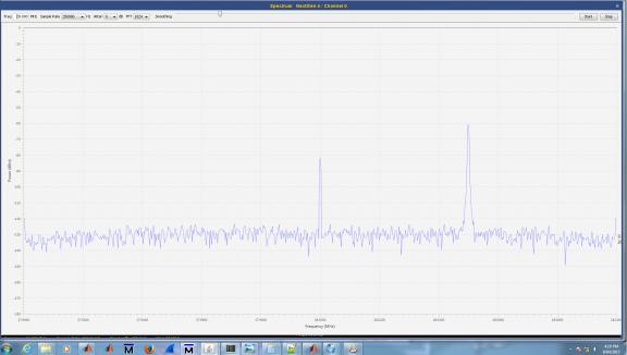
Link Copied
14 Replies
- Mark as New
- Bookmark
- Subscribe
- Mute
- Subscribe to RSS Feed
- Permalink
- Report Inappropriate Content
Looks like you have overlooked dc gain in your system. Most likely your cic filter.
In fact cic filter or fir or mixer must take care of dc. for cic dc gain = (R*M)^N (R = 64 in your case, M is comb stages, N = cascade stages). If dc gain is only due to cic then if (R*M)^N is power of 2 you can discard lsbs to get unity dc gain and so avoid designing division. For fir if sum of coeffs = 1 (normalised) then it is ok otherwise rescale them.- Mark as New
- Bookmark
- Subscribe
- Mute
- Subscribe to RSS Feed
- Permalink
- Report Inappropriate Content
Hi Kaz,
Thanks a lot for the reply. Lee- Mark as New
- Bookmark
- Subscribe
- Mute
- Subscribe to RSS Feed
- Permalink
- Report Inappropriate Content
Hi Kaz,
How to reduce DC in the mixer stage? I think my dc is generated from the mixer stage. I checked the baseband I and the 0 frequency is -5 dbm and (+-)50KHz is +66 dbm when the noise level is about -47 dbm. I guess I need to reduce the DC to around noise level. These results are from ModelSim. (Note the digram above is from the FPGA not modelsim). I have discarded 28 bits from the cic output so the DC should be not from cic. The sum of fir coefficient is 4. I will rescale it to 1. Many Thanks, Lee- Mark as New
- Bookmark
- Subscribe
- Mute
- Subscribe to RSS Feed
- Permalink
- Report Inappropriate Content
You can check dc gain of CIC and FIR by injecting it with step input.
if you can't achieve unity by discarding LSBs then you can rescale FIR to any value compensate for overall gain. Mixer will cause dc if there is power in a frequency that is shifted to dc at mixing. For example if your NCO is at 1MHz then any power in 1MHz (or its multiples) will move to dc (or alias to dc). You wiil then need LPF before mixing.- Mark as New
- Bookmark
- Subscribe
- Mute
- Subscribe to RSS Feed
- Permalink
- Report Inappropriate Content
Hi Kaz,
Thanks for the comments. I will update you how we actually solved the DC issue next week. Lee- Mark as New
- Bookmark
- Subscribe
- Mute
- Subscribe to RSS Feed
- Permalink
- Report Inappropriate Content
Hi Kaz,
My DC issue was mainly happening in the mixing. I have attached the matlab plot of my baseband results. The input is 28.05 MHz which is 124 dBm above 28MHz where as the nco 28 MHz cosine/sin is 115 dBm above 28.05MHz. These show that the input and nco sin/cos does not cause major DC. However, in the 16 bit baseband result (i+j*Q), the DC is 1 dBM and the 50KHz peak is 82 dBm. This is a strong DC. Interestingly, in the 32 bit baseband plot, the DC has been reduced to -71dBm. This shows that increase in the baseband bit width reduces the DC significantly. Do you have any idea why? Many Thanks, Lee
- Mark as New
- Bookmark
- Subscribe
- Mute
- Subscribe to RSS Feed
- Permalink
- Report Inappropriate Content
I think you are confused.
dBm has no meaning here, you probably mean dB. Even dB depends on how you see spectrum. Don't worry about these figures. Why you mention nco cosine only? I expect nco to be cos/sin what matters is this: Your input signal is centred at 28.05MHz and is real only I assume. Ok what s your nco frequency? that is the key to any dc. if your nco is -28.05 or +28.05 then you are pushing signal to dc- Mark as New
- Bookmark
- Subscribe
- Mute
- Subscribe to RSS Feed
- Permalink
- Report Inappropriate Content
Hi Kaz,
NCO's sin and cos frequency is 28MHz. So the baseband signal has a strong peak at 50KHz (28.05 - 28 MHz = 50 KHz). 28.05 MHz Input bit width: 16 bits 28 MHz NCO bit width: 16 bits The 32 bit baseband signal (I+j*Q) shows the relatively small DC. But 16 bit baseband (casting the lower 16 bits) shows very strong DC, as shown in the plot above . Why is that? Many Thanks, Lee- Mark as New
- Bookmark
- Subscribe
- Mute
- Subscribe to RSS Feed
- Permalink
- Report Inappropriate Content
you should keep the MSBs otherwise you distort the signal. remove 15 LSBs.
- Mark as New
- Bookmark
- Subscribe
- Mute
- Subscribe to RSS Feed
- Permalink
- Report Inappropriate Content
I used 16 MSBs and still got strong DC.
- Mark as New
- Bookmark
- Subscribe
- Mute
- Subscribe to RSS Feed
- Permalink
- Report Inappropriate Content
That is what you should get by design. you are moving input tone at 20.05MHz using nco at 20MHz so you should expect output to be at 50KHz. This is not dc per se but your design target.
- Mark as New
- Bookmark
- Subscribe
- Mute
- Subscribe to RSS Feed
- Permalink
- Report Inappropriate Content
Hi Kaz,
I got two major peaks in the 16 bit baseband signal. The main peak is 82 dB at 50 KHz and the second peak is 1 dB of DC whereas the noise level is around -100 dB. This 1dB DC is not acceptable. Once I extended the baseband signal to 32 bits, the DC reduced to -71 dB where as the 50KHz still still the same 82 dB. This reduced DC is what I want. I just have no idea why extending the baseband bit width reducing the DC level. I copied this technique from a project without knowing what is the theory behind it. Lee- Mark as New
- Bookmark
- Subscribe
- Mute
- Subscribe to RSS Feed
- Permalink
- Report Inappropriate Content
such tiny dc spike is likely due to truncation. do rounding instead of direct truncation. Normal rounding will do. alternatively do dc non-biased rounding.
- Mark as New
- Bookmark
- Subscribe
- Mute
- Subscribe to RSS Feed
- Permalink
- Report Inappropriate Content
Thanks for the comments
Reply
Topic Options
- Subscribe to RSS Feed
- Mark Topic as New
- Mark Topic as Read
- Float this Topic for Current User
- Bookmark
- Subscribe
- Printer Friendly Page