- Mark as New
- Bookmark
- Subscribe
- Mute
- Subscribe to RSS Feed
- Permalink
- Report Inappropriate Content
Hi,
My requirement is keep the transceiver lines in Electrical Idle whenever the Logical Layer FSM goes into low power state.
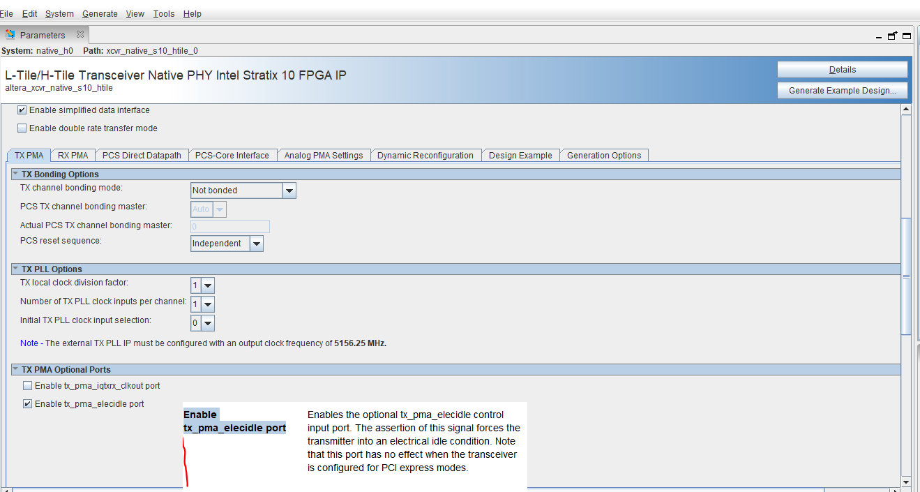
I found that we can select "Enable tx_PMA_elecidle port" under TX PMA configuration of native PHY IP. Note that I am using this native Phy for non-PCIe application (in PCS Direct mode).
My question is,
a) What is the behavior of Transceiver p/n lines when I drive tx_PMA_elecidle = 1;
b) Is there any specific steps involved for enabling and disabling tx_PMA_elecidle port? (I didn't find any timing diagram to handle the port in the Stratix 10 L-tile transceiver user-guide.)
With regards,
HPB
Link Copied
- Mark as New
- Bookmark
- Subscribe
- Mute
- Subscribe to RSS Feed
- Permalink
- Report Inappropriate Content
Hi HPB,
As I understand it, you have some inquiries related to the tx_pma_elecidle for S10 L-Tile XCVR for non-PCIe mode. Please see my responses to your inquiries as following:
a) What is the behavior of Transceiver p/n lines when I drive tx_PMA_elecidle = 1;
[CP] The transmitter will be tri-stated when this signal is driven high.
b) Is there any specific steps involved for enabling and disabling tx_PMA_elecidle port? (I didn't find any timing diagram to handle the port in the Stratix 10 L-tile transceiver user-guide.)
[CP] No. No specific steps or timing diagram for non-PCIe mode.
Please let me know if there is any concern. Thank you.
Best regards,
Chee Pin
- Mark as New
- Bookmark
- Subscribe
- Mute
- Subscribe to RSS Feed
- Permalink
- Report Inappropriate Content
Hi @cheepinc_Intel ,
Thank you for clarifying when tx_PMA_elecidle = 1, the transmitter will be tri-stated.
I have a requirement that the Transmitter to be in electrical IDLE for 100ns and after that the transmitter resumes its usual traffic. So, in order to keep the transmitter in electrical IDLE, should I make port tx_PMA_elecidle = 1 for 100ns, and drive the tx_PMA_elecidle = 0 afterwards?
With regards,
HPB
- Mark as New
- Bookmark
- Subscribe
- Mute
- Subscribe to RSS Feed
- Permalink
- Report Inappropriate Content
- Mark as New
- Bookmark
- Subscribe
- Mute
- Subscribe to RSS Feed
- Permalink
- Report Inappropriate Content
Hi,
I need one clarification regarding below point.
a) What is the behavior of Transceiver p/n lines when I drive tx_PMA_elecidle = 1;
[CP] The transmitter will be tri-stated when this signal is driven high.
When transmitter is tri-stated, whether common mode voltage will be maintained in the transmitter line (note that I am not enabling any PIPE/PCIe related settings, instead Native PHY will be configured with PCS Direct mode)?
With regards,
HPB
- Mark as New
- Bookmark
- Subscribe
- Mute
- Subscribe to RSS Feed
- Permalink
- Report Inappropriate Content
Hi,
Also, when Transmitter in Electrical IDLE, whether txuserclock toggling will be valid?
If the Transmitter in electrical IDLE is loopback to a receiver, In this case, receiver also provide valid rxuserclock as required to configured data rate?
With regards,
HPB
- Mark as New
- Bookmark
- Subscribe
- Mute
- Subscribe to RSS Feed
- Permalink
- Report Inappropriate Content
- Mark as New
- Bookmark
- Subscribe
- Mute
- Subscribe to RSS Feed
- Permalink
- Report Inappropriate Content
Hi HPB,
As I understand it, when the TX buffer is put to electrical idle, the output voltage should be the common mode voltage. However, I have not physically measured this in hardware, you might need to perform hardware measurement to double check on this. Sorry for the inconvenience.
Best regards,
Chee Pin
- Mark as New
- Bookmark
- Subscribe
- Mute
- Subscribe to RSS Feed
- Permalink
- Report Inappropriate Content
Hi HPB,
Regarding your latest inquiries on the txuserclock, please correct me if I am wrong, I believe you are referring to the XCVR-core parallel clock ie tx_clkout. If yes, as I understand it, when the TX is put to elecical idle, the tx_clkout should be still valid as it is derived from the TX PLL which is still working.
Regarding the loopback, since there is no valid data received by RX, the CDR would not be able to lock-to-data. It will remain locking to its own reference clock and the rx_clkout will be derived from its own reference clock.
Please let me know if there is any concern. Thank you.
Best regards,
Chee Pin
- Mark as New
- Bookmark
- Subscribe
- Mute
- Subscribe to RSS Feed
- Permalink
- Report Inappropriate Content
Hi Chee Pin,
Yes, I was talking about parallel clock.
I am convinced that tx_clkout will be valid as it is generated by local ATX PLL.
On the receiver side, I am not clear about "remain locking to its own reference clock" .
Does this mean that Lock-to-Reference Mode (rx_is_lockedtoref =1)? If this is true, then frequency of rx_clkout is same as frequency of reference clock?
With an example, I will explain my understanding. Please correct me if I am wrong.
Reference clock frequency = 156.25Mhz
Before RX receives electrical IDLE, it was locked to data @ 20Gbps data rate & 64-bit interface. So rx_clkout = 20G/64 = 312.5MHz.
When RX receives electrical IDLE, then there is no data toggling and hence rx losses lock to data. Then rx_clkout will be only locked to its reference clock. Whether that means, rx_clkout will be changed to 156.25MHz from 312.5MHz?
If the corresponding TX is out of electrical IDLE, then RX again locks to data and switches back to 312.5Mhz?
With Regards,
HPB
- Mark as New
- Bookmark
- Subscribe
- Mute
- Subscribe to RSS Feed
- Permalink
- Report Inappropriate Content
Hi HPB,
Yes, your understanding of the lock-to-ref is correct. When there is no valid data at the RX, the CDR will in LTR mode. Note that in actual hardware, you may see this rx_is_lockedtoref and rx_is_lockedtodata toggle periodically because the CDR will attempt to lock-to-data from time to time.
Regarding the frequency of the rx_clkout, the output frequency will stay at 312.5MHz even though it is in LTR mode. It is following 20G/64. When CDR achieves lock-to-data, it is tracking the ppm difference between the incoming data and the RX local refclk. The nominal frequency will still be 312.5MHz with some ppm difference only.
Please let me know if there is any concern. Thank you.
Best regards,
Chee Pin
- Subscribe to RSS Feed
- Mark Topic as New
- Mark Topic as Read
- Float this Topic for Current User
- Bookmark
- Subscribe
- Printer Friendly Page