- Mark as New
- Bookmark
- Subscribe
- Mute
- Subscribe to RSS Feed
- Permalink
- Report Inappropriate Content
Hi,
I am trying to rewrite C routine for ethernet (sending of a packet) to VHDL. And I would like to know, how can I write command for setting up some configuration in ethernet driver registry. For example I have this function in C:
void iow(unsigned int reg, unsigned int data) {
  IOWR(DM9000A_BASE,IO_addr,reg);
  usleep(STD_DELAY);
  IOWR(DM9000A_BASE,IO_data,data);
}
Specifically without constant:
void iow(unsigned int reg, unsigned int data) {
  IOWR(0x11000,0,0x01);
  usleep(20); //us
  IOWR(0x11000,1,0xFF);
}
In the datasheet for DM9000A there are pins: iow (write), cs (chipselect), cmd (commad - index or data), sd0~7 (data) In compare with C: iow = IOWR cmd = IO_ADDR or IO_DATA sd0~7 = reg or data in argument of function So VHDL should be:
iow <= '0' -- active in low for writting
cs <= '0' -- active in low
cmd <= '0' -- i want to write index
... -- delay 10ns
sd <= x"01" -- i want registry with offset 0x01
.. -- delay 20us
cmd <= '1' -- i want to write data
... -- delay 10ns
sd <= x"FF" -- i want set registry to value 0xFF
And my questions are: What is correct way to implement this? How can I implement a delay like usleep() in C? Can I put this sequence in VHDL to some procedure? I would be glad for your advice
Link Copied
- Mark as New
- Bookmark
- Subscribe
- Mute
- Subscribe to RSS Feed
- Permalink
- Report Inappropriate Content
Synthesizable VHDL has no concept of delays or sequential programming like in C.
Only things that can be implemented with sequential (flip-flops, RAM) and combinatory logic. Therefore, you need to implement a state machine and counters to implement the delay. Something like this: process (clk) -- 100 MHz clock, 10 ns period if rising_edge(clk) then if state = state:1 then iow <= '0'; cs <= '0'; cmd <= '0'; state <= state_2; elsif state = state_2 then sd <= x"02", delay_counter <= 2000; -- 2000 * 10 ns = 20 µs state <= state_3; elsif state = state3 then if counter = 0 then state <= state_4; else counter <= counter - 1; elsif state = state_4 then cmd <= '1'; state <= state_5; elsif state = state_5 then sd <= x"FF; ... end if; end process- Mark as New
- Bookmark
- Subscribe
- Mute
- Subscribe to RSS Feed
- Permalink
- Report Inappropriate Content
And is it appropriate to use a state machine with a lot of states if I have more these "register settings"? Or I should use for example procedure set_reg(reg,value)? I am afraid of its influence on the complexity of structure in FPGA.
- Mark as New
- Bookmark
- Subscribe
- Mute
- Subscribe to RSS Feed
- Permalink
- Report Inappropriate Content
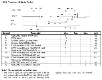
As a first point, you should study the DM9000 bus timing requirements. Your above example won't work correctly, because it doesn't keep the IOW setup- and hold times. Using a state machine for the elementary read and write access sequence sounds reasonable. Most likely a second state machine should be responsible to schedule the command sequences.
- Mark as New
- Bookmark
- Subscribe
- Mute
- Subscribe to RSS Feed
- Permalink
- Report Inappropriate Content
FVM:
In the attachment, there is a timing of DM9000A IOW, I suppose that there is a requirement for setup and holt time only in "sd" data case (10ns for setup and 3ns for hold)? And as you said - second state machine, do you thing something like this (example)? I think If I have a maximum delay 10ns, so one clk period with 50MHz frequency (T = 20ns) should be enough, right?
IF (clk'EVENT AND clk = '1') THEN
         CASE state IS
            WHEN s0=>
               IF input = '1' THEN
                  state <= s1;
               ELSE
                  state <= s0;
               END IF;
            WHEN s1=>
               IF input = '1' THEN
                  state <= s2;
               ELSE
                  state <= s1;
               END IF;
            WHEN s2=>
               IF input = '1' THEN
                  state <= s0;
               ELSE
                  state <= s2;
               END IF;
         END CASE;
      END IF;
   END PROCESS;

   PROCESS (state)
   BEGIN
      CASE state IS
         WHEN s0 =>
            -- delay 10ns
         WHEN s1 =>
            -- delay 20ns
         WHEN s2 =>
            -- delay 5us
      END CASE;
   END PROCESS;
* sorry for small image in the attachment, I haven't got enough of posts for url.
- Mark as New
- Bookmark
- Subscribe
- Mute
- Subscribe to RSS Feed
- Permalink
- Report Inappropriate Content
--- Quote Start --- I suppose that there is a requirement for setup and holt time only in "sd" data case --- Quote End --- Your initial example is also violating T1. There are some more points to consider, I won't elaborate a single detail now. If you want to squeeze DM9000 timing, you possibly should provide a faster clock for the state machine. Or implement double data rate output registers for some signals to achieve a finer timing control. P.S.: I just realized the difference between DM9000 (which I previously used) and DM9000A. The timing has been considerably improved.
- Mark as New
- Bookmark
- Subscribe
- Mute
- Subscribe to RSS Feed
- Permalink
- Report Inappropriate Content
I found out, that if I want to intialize DM9000A from Nios, I have to solve some addressing.
My intention is to make a interface which receives data from stream, makes a ethernet packet from data and sends it to the DM9000A. But at the beginning I have to initialize my "transceiver" with MAC, IP address, IP header... and DM9000 with some settings too (interrupts, etc). I have Avalon master -> my VHDL transceiver -> DM9000A, transceiver is addressable, but DM9000A not. So I have to place some bidirectional Avalon parallel I/O port between my transceiver and DM9000A because of addressing its ports from Nios. Summary: 1. Initialize my transceiver from Nios 2. Initialize DM9000A from Nios via parallel port between transceiver and DM9000A 3. No more initalizion. Transfer data from stream to DM9000A Is Avalon parallel port in front of DM9000A right way for initialization at the beginnig?- Subscribe to RSS Feed
- Mark Topic as New
- Mark Topic as Read
- Float this Topic for Current User
- Bookmark
- Subscribe
- Printer Friendly Page