- Mark as New
- Bookmark
- Subscribe
- Mute
- Subscribe to RSS Feed
- Permalink
- Report Inappropriate Content
Hello,
I am trying to work with VIP suite. My main objective is to read YCbCr 4:2:2 progressive 720x576 image from HPS DDR3 into the VIP suite using Frame reader , interlace the frame reader output , serialize the output and send it to ADV chip using CVO. I'm running the VIP IPs at 27Mhz and the memory read is at 216Mhz. I tested this flow HPS DDR3->FR->ITL->CVO using the VIP, underflow in CVO output detected with non valid image output. To check the path error I have put signal tap into the project and suspected Interlacer output. I tried using test pattern generator , TPG(YcbCr,4:2:2,sequence,interlaced output)->CVO I get proper color pattern output. I then tried , TPG(YcbCr,4:2:2,progressive,parallel)->ITL->CPS->CVO , I get CVO underflow and the output image is not proper. Can anyone tell me the correct usage of Interlacer IP ? I read in the VIP userguide that it works with odd heights of the image?If it is so how can i go about getting a valid output? Any leads would be greatly appreciated. Thankyou and Regards, VidyaLink Copied
- Mark as New
- Bookmark
- Subscribe
- Mute
- Subscribe to RSS Feed
- Permalink
- Report Inappropriate Content
Is the CVO matching the stream you're supplying it? Look at the CVO registers and see if they can tell you more about why it doesn't like your input stream.
- Mark as New
- Bookmark
- Subscribe
- Mute
- Subscribe to RSS Feed
- Permalink
- Report Inappropriate Content
Hi Ted,
Thanks Ted for your reply. All the mode configuration registers of CVO read 1 and the underflow bit is also 1. Also I have noticed the CVO input video packet, the control packet data alternates between 0F,00,02,0D,00,01,02,00,0F,00 and 0F,00,02,0D,00,01,02,00,0B,00. According to the above data packets , width = 2D0h= 720 ,height =120F /120B = 4623/ 4619 I do not understand the height part of the packet . Is it correct? Following are my CVO settings image width: 720 image height: 576 Bits per pixel per color plane: 8 Number of color planes: 2 Color plane format: sequence Allow output channels in sequence : checked Interlaced video: checked Syncs signals: Embedded in video Active picture line: 23 Field 1 Ancillary packet insertion line :8 Embedded syncs-Field1 Horizontal blanking :144 Vertical blanking :2 Interlaced and field 0 parameters F rising edge line :313 F falling edge line :1 Vertical blanking rising edge line :311 Ancillary packet insertion line :321 Embedded syncs Field 0 Vertical blanking :24 lines pixel fifo size: 55296 (4 times [(1440+288)*8])i.e 4 lines of data Fifo level : 55295 I have tried various combinations but the output does not appear proper and the underflow bit is always high. Video in and out use same clock: checked Use control port : checked Runtime configurable video modes : 1 modes Width of vid_bus :1 bits Regards, Vidya- Mark as New
- Bookmark
- Subscribe
- Mute
- Subscribe to RSS Feed
- Permalink
- Report Inappropriate Content
--- Quote Start --- Also I have noticed the CVO input video packet, the control packet data alternates between 0F,00,02,0D,00,01,02,00,0F,00 and 0F,00,02,0D,00,01,02,00,0B,00. According to the above data packets , width = 2D0h= 720 ,height =120F /120B = 4623/ 4619 I do not understand the height part of the packet . Is it correct? --- Quote End --- No, it is not correct. Did you transcribe the packet data incorrectly?
0F,00,02,0D,00,00,01,02,00,0F
0F,00,02,0D,00,00,01,02,00,0B
The above packet would have made more sense (trailing 0F and 0B are the interlacing fields for F0/F1 frames). And height 0120h=288 = (576/2)
- Mark as New
- Bookmark
- Subscribe
- Mute
- Subscribe to RSS Feed
- Permalink
- Report Inappropriate Content
Hi Ted,
You are right. I transcribed the packet data wrongly by missing 00 which is valid for two clock cycles. But then I can not figure why the CVO is underflowing. I'm attaching the output with CVO fifo depth 720, start size 719 namely TPG_CVO_output1.bmp and the output with CVO fifo depth 13824 , start size 13823 namely TPG_CVO_output2.bmp Can you help me in figuring out where the problem could be? Thanks & Regards, Vidya- Mark as New
- Bookmark
- Subscribe
- Mute
- Subscribe to RSS Feed
- Permalink
- Report Inappropriate Content
Without thinking about it too much, "bigger buffer gave better result" so place a Frame Buffer IP directly before the CVO. If that works, then all your parameters regarding video/stream formats are correct and your issue is simply clock/buffer related. As the CVO is underflow, that means it is draining data faster than it is receiving it, but I'm not sure why that would be based on your previous description of your system. Anyway, adding a Frame Buffer should give you some clue.
- Mark as New
- Bookmark
- Subscribe
- Mute
- Subscribe to RSS Feed
- Permalink
- Report Inappropriate Content
Hi Ted,
I tried with Frame buffer in front of CVO. I get the output as in TPG_VFB_CVO.bmp with rolling video. The test pattern that I see is not the same as given in the VIP user guide Test pattern generator output. Also I have attached signal tap signals capture vip_osd.jpg. You can see that the CVO underflows during 17th line. Can this mean something ? I'm clueless here. Thanks & Regards, Vidya- Mark as New
- Bookmark
- Subscribe
- Mute
- Subscribe to RSS Feed
- Permalink
- Report Inappropriate Content
It means your CVO is sinking data faster than your frame buffer is sourcing it. I am guessing your frame buffer Avalon-MM ports are either running too slow or configuration mismatches resulting in inefficient operation of the memory interface?
You'll want to make sure the frame buffer has frame repeating enabled, and then you may want to end up with the Avalon-MM Master ports running on a separate (faster) clock domain than the Avalon-ST ports. Basically, you need to make sure the frame buffer is configured correctly and it has adequate resources to fetch data faster than the CVO can process it. You can do this with either faster clocks or with wider Avalon-MM width. In normal use, the frame buffer should be more than capable of keeping the CVO FIFO nearly full for the entire frame. From your original post, it sounds like you want CVO clock 27MHz with 16bpp. If your DDR3 is 216MHz, your Avalon-MM is probably half that but double wide (108MHz, 32-bit ? 64-bit?) This is plenty of capacity as long as the frame buffer is using the separate clock domain for the Avalon-MM ports and is using bursts to stream the data. If you've already checked all these things, you can increase the depth of the frame buffer FIFO's and burst lengths and confirm they have an impact on your 17th row underflow.- Mark as New
- Bookmark
- Subscribe
- Mute
- Subscribe to RSS Feed
- Permalink
- Report Inappropriate Content
Hi Ted,
Thanks a lot for your suggestions. I tried with frame repetition on and increased the Frame buffer Avalon MM write and read fifo sizes. Now I get a proper test pattern at the output with no underflow of CVO but still it seems to be somewhat distorted. I have attached the output image. Could it be the problem with any other CVO or Frame buffer setting? Regards, Vidya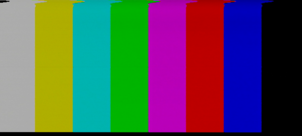
- Mark as New
- Bookmark
- Subscribe
- Mute
- Subscribe to RSS Feed
- Permalink
- Report Inappropriate Content
I'm not sure what that distortion is. However, if you've got no underflow, you are done configuring the Frame Buffer and your issue is elsewhere.
Can you summarize your processing chains? TPG->CVO = works, no artifact ? TPG->VFB->CVO = artifact shown in TPG_VFB_CVO3.bmp ?- Mark as New
- Bookmark
- Subscribe
- Mute
- Subscribe to RSS Feed
- Permalink
- Report Inappropriate Content
Hi Ted,
My processing chain is summarized as below: TPG->ITL->CPR->CVO , No proper test pattern output plus CVO underflow bit is high. TPG->ITL->CPR->VFB->CVO, Proper test pattern with distortion(artifact) , underflow bit is low. Regards, Vidya- Mark as New
- Bookmark
- Subscribe
- Mute
- Subscribe to RSS Feed
- Permalink
- Report Inappropriate Content
In the first post of the thread, you mentioned:
--- Quote Start --- I tried using test pattern generator , TPG(YcbCr,4:2:2,sequence,interlaced output)->CVO I get proper color pattern output. --- Quote End --- My suggestion would be to briefly retest that configuration and confirm that no distortion appears. If that configuration works well, it would point toward the addition of ITL+CPR blocks causing the issue. If TPG->CVO has the same distortion, then the issue is probably with the CVO not matching your hardware/display. Good luck.- Mark as New
- Bookmark
- Subscribe
- Mute
- Subscribe to RSS Feed
- Permalink
- Report Inappropriate Content
The interlacer core creates an interlaced output by dropping every other line in the incoming progressive frames. So the interlacer output field rate is equal to the progressive frame rate, but the data rate is cut in half. If you're running the ITL and CVO cores at the same clock rate then the CVO pretty much has to underflow. The CVO is driving a display so it can't be starved. Your pipeline works with the TPG because the TPG is generating interlaced fields natively instead of taking in a progressive frame and discarding every other line (which means the CVO core input is starved 50% of the time). If you run the ITL core at 2x the CVO core clock rate the pipeline should work.
By the way, color bars is a bad test pattern to evaluate interlacing because every row of the test pattern is identical. You should try it with a pattern that has some variation vertically. One other point. You could interlace properly (meaning that each progessive frame produces two interlaced fields) by perferming the interlacing on the way out of DDR3. Just read even lines out of the frame buffer to produce even fields then odd lines to produce odd fields. This would require some custom logic to read the fields from memory, but then you could feed data directly to the CVO.- Mark as New
- Bookmark
- Subscribe
- Mute
- Subscribe to RSS Feed
- Permalink
- Report Inappropriate Content
Thank you very much rsefton and Ted.
The test pattern generator output works fine with the pipeline running @54Mhz and the CVO pixel clock @27Mhz. The distortion or artifact was because of the display device, I changed the display device and the output looks perfectly fine. Now I shall proceed to testing with frame reader and mixer. Regards, Vidya- Subscribe to RSS Feed
- Mark Topic as New
- Mark Topic as Read
- Float this Topic for Current User
- Bookmark
- Subscribe
- Printer Friendly Page