- Mark as New
- Bookmark
- Subscribe
- Mute
- Subscribe to RSS Feed
- Permalink
- Report Inappropriate Content
Hello All,
I have an interesting problem. I've managed to put together a video processing path: cvi->scaler->frame buf->cvo Which works reasonably well scaling SXGA to SVGA for display on an LCD. Very simple. See 1st image below image. i then add a nios2/e with the standard JTAG UART and sysid peripherals. For ease I'm using 4k of on chip ram. I've connected the control port to all the above blocks. For the result look at the 2nd image below. This has only happened since upgrading my Quartus to 9.1. The sp1 upgrade did not fix the issue. It appears that instead of a line of 800 pixels arriving at the cvo, i'm getting 800 + n (where 5 > n > 10). This causes the square to be splayed diagonally. I've built this dozens of times with different size fifos on the cvo/cvi, and I think that my timing constraints are ok. See attached my sopc config. If I reduce the incoming SXGA signal by a few pixels (never consistent between builds) then the image lines up again and looks normal. But resetting the sopc will cause the distortion again. It's like the sopc is auto-detecting x pixels each time it comes out of reset, and then outputting x + n. Another note is that bit 10 of the cvi status register never sets - indicating that a valid resolution is never detected. My HS & VS signals are both logic +ve, and they only occur when the data_valid signal is 0 so they should be disturbing a frame. i've checked the data_valid window against the incoming pixel clock and it measures a perfect 1280px (or what ever I set the video to) and is stable with expected jitter and good amplitude. Has anyone see this issue before? did any of the vip ip blocks change so significantly between 9.0 and 9.1 as to cause this issue? All help greatly appreciated, thanks in advance. Cheers, Brent.- Tags:
- Define
Link Copied
- Mark as New
- Bookmark
- Subscribe
- Mute
- Subscribe to RSS Feed
- Permalink
- Report Inappropriate Content
One other thing: I can only ever read 0xffffffff from the scaler registers; including the status register!!
- Mark as New
- Bookmark
- Subscribe
- Mute
- Subscribe to RSS Feed
- Permalink
- Report Inappropriate Content
BREAKING DEVELOPMENT:
if i pull the control port out of the scaler, and just let it do it's thing default, it corrects the skew problem. Question: what am I missing with the scaler? I'm executing these lines ONLY for the scaler to initialise: void scaler_enable(void){
iowr( scaler_base, control, vip_stop );
iowr( scaler_base, scaler_reg_size_x, l2_x_size );
iowr( scaler_base, scaler_reg_size_y, l2_y_size );
iowr( scaler_base, control, vip_go );
}
and for readback:
alt_printf( "\nscaler registers:\n" );
alt_printf( " control: %x\n", iord( scaler_base, control ) );
alt_printf( " status: %x\n", iord( scaler_base, status ) );
alt_printf( " size x: %x\n", iord( scaler_base, scaler_reg_size_x ) );
alt_printf( " size y: %x\n", iord( scaler_base, scaler_reg_size_y ) ); where: #define scaler_reg_control 0
# define scaler_reg_status 1
# define scaler_reg_size_x 2
# define scaler_reg_size_y 3
- Mark as New
- Bookmark
- Subscribe
- Mute
- Subscribe to RSS Feed
- Permalink
- Report Inappropriate Content
--- Quote Start --- One other thing: I can only ever read 0xffffffff from the scaler registers; including the status register!! --- Quote End --- Maybe you just posted the wrong image, but I do not see a control port for the scaler in your SOPC system.
- Mark as New
- Bookmark
- Subscribe
- Mute
- Subscribe to RSS Feed
- Permalink
- Report Inappropriate Content
Adding the control port to the scaler does more than just enable you to control the scaling ratio and set the go bit.
It also enables runtime control of the scaler, meaning that it enables the logic within the scaler that decodes the VIP control packets on the streaming interface and automatically determine the input video height and width. Without this, the scaler just always assumes the input resolution is what you declared in the megawizard. Have you looked at the video control packets coming out of the CVI and made sure they are correct? If the CVI is not correctly detecting your video input resolution, this would likely explain all of your issues. P.S. Send me your design. We'll fix you up. Jake- Mark as New
- Bookmark
- Subscribe
- Mute
- Subscribe to RSS Feed
- Permalink
- Report Inappropriate Content
Hi Jake,
How do I tap and read the control packets? I'll zip up and post my project to you asap. Thanks for your help... again!- Mark as New
- Bookmark
- Subscribe
- Mute
- Subscribe to RSS Feed
- Permalink
- Report Inappropriate Content
Use signaltap on the avalon streaming output of the CVI (data, datavalid, startofpacket, endofpacket, ready). The avalon control packets begin with a data field of 0xf asserted with startofpacket and datavalid. Refer to page 4-7 of the user's guide:
http://www.altera.com/literature/ug/ug_vip.pdf Jake- Mark as New
- Bookmark
- Subscribe
- Mute
- Subscribe to RSS Feed
- Permalink
- Report Inappropriate Content
Is there any way to enable Incremental Compilation with the 'web' edition of Quartus II? The re-compile times are going to make this difficult...
- Mark as New
- Bookmark
- Subscribe
- Mute
- Subscribe to RSS Feed
- Permalink
- Report Inappropriate Content
Here is a screengrab from SignalTap. FYI, my path has 3 colour planes in parallel 4bits wide each. I tapped the input to the scaler, which below the CVI in the system. Looks like the control packets are ok:
- width = 0x04F9= 1273 pixels which is acceptable - (but should be 1280 strictly) - height = 0x0400 = 1024 lines which is perfect - interlacing field = 0x2, progressive which is correct. The packets are consistent, but only occur once, when the VIP is turned on, shouldn't these occur more frequently? Or does a control packet only occur when there is a change in settings? I'm going to re-introduce the control port on the scaler, then tap it's output, then successively each downstream.
- Mark as New
- Bookmark
- Subscribe
- Mute
- Subscribe to RSS Feed
- Permalink
- Report Inappropriate Content
The width of 1273 is not acceptable because it's wrong. Also, you should get a control packet at the beginning of every single frame of video. It really seems to me that the CVI is not able to detect your video input properly.
I'm working on trying to get your project setup to work on a board that I've got. In my case, I'm going to fake the video input with a generator feeding into the CVI. I have a board with a DVI input and a DVI output but I don't want to dust it off. Jake- Mark as New
- Bookmark
- Subscribe
- Mute
- Subscribe to RSS Feed
- Permalink
- Report Inappropriate Content
Hi Jakob,
Attached are some fresh screen grabs of my video signals. These are signals coming out of the FPGA though some spare pins that i have for TAP purposes. You'll see the calculated measurements of the signal on the grabs. There is a bit of jitter, about +/- 100ps which I think it good for a recovered clock. Given that my mean pixel clock is 108.9MHz, DE +ve period is 11.75us I should clock in 1279.6 pixels. The 0.4 pixels is acceptable error. I guess you are correct, seeing 1273 pixels in the control packet could be a symptom of a problem... I've also attached another SignalTap grab, this time coming out of the scaler (with control port attached). The final image on the LCD is exhibiting similar image distortion to that described above. The control packet reads: - width 1273 px - height 1024 lines - progressive It's the same as the control packet that I saw entering the scaler!? Also, the dout_valid signal is dipping a lot, does this look normal? Could all this come from having exceeded the fmax of the system? (TimingQuest says no) - is the scaler just not turning on?- Mark as New
- Bookmark
- Subscribe
- Mute
- Subscribe to RSS Feed
- Permalink
- Report Inappropriate Content
I didn't realise it but there is another control packet, not long after the 1st one, coming out of the scaler. The second one contains the a correct control packet with width and height that I can control through the Nios2. See attached image.
Could this be because the scaler can't keep up with the input? My cvi fifo is currently 1280px, or one line. This is sensible as there are about 400 px of sync/blanking period in which no pixels are clocked in, and in this time the fifo should drain down - perhaps not enough? I've got the scaler running off the pixel clock at the moment, I'm going to compile a design now where the video path is clocked 10% faster than the pixel clock, from a different base clock.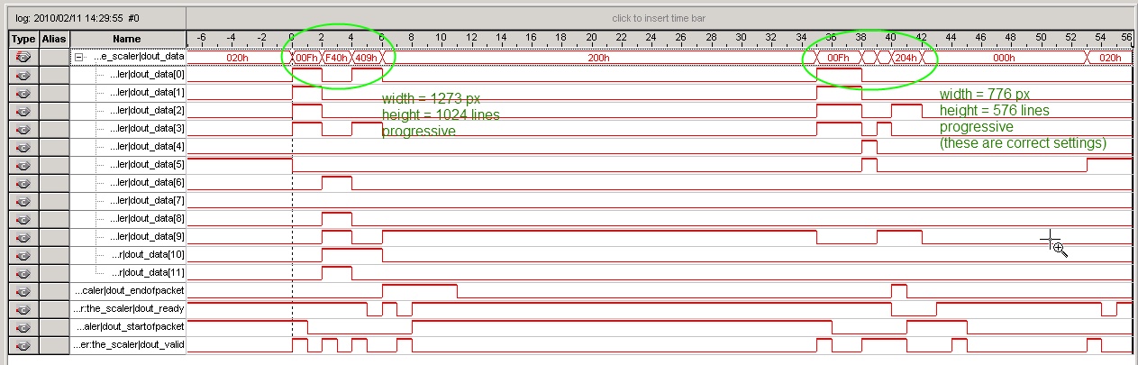
- Mark as New
- Bookmark
- Subscribe
- Mute
- Subscribe to RSS Feed
- Permalink
- Report Inappropriate Content
The behavior of the VIP cores is often to pass all control packets through. So for example, the deinterlacer will pass the original interlaced control packet followed by the new control packet. The scaler likely does the same thing. So it's passing the control packet that it received from upstream, then it's sending it's own control packet for the frame that it has just scaled. That is why you see two.
You're image is slanting down and to the left. Which indicates that you are dropping pixels. This points to overflowing the input FIFO. You ought to be able to probe with signaltap for this (or read the status register). Look at the image. Would you say your losing about 7 pixels per line? Doesn't the CVI have an overflow output that you can observe? If you are overflowing the input FIFO, then yes the solution is to increase the processing of the video. Specifically, you need to get it out of the CVI, through the scaler, and into the frame buffer faster. It could very well be that adding the runtime control to the scaler pushed you over the edge because now the scaler has to decode the incoming control packets. Jake- Mark as New
- Bookmark
- Subscribe
- Mute
- Subscribe to RSS Feed
- Permalink
- Report Inappropriate Content
Hi Guys,
I think that the CVI is confused, but I don't think that this is causing the image distortion. The main reason why is that without the control of the scaler, the system works. Unfortunately, I do need control of the scaler for our applicaiton; it's the main reason why we are not using off the shelf equipment for our application. Jake, the screen is upside down; the picture shows the top left of the screen, but the back of it. So there are extra pixels, pushing it to the right of the screen (from the front viewpoint). I should have put this note on the images, or flipped them for logical purposes. I am getting both overflow on cvi and underflow on my video out, but it is inconsistent, here is the outputs from my cvi and cvo registers as they are most recently reported by nios2 code (some are derived): Vid In Registers: Running Stable OVERFLOW Invalid Resolution Used Words: 0 A. Sample Cnt: 400 A. Line Count: 2f7 T. Sample Cnt: 540 T. Line Count: 324 Vid Out Registers: Control: 1 Status: 5 Interrupt: 0 Used Words: 4af Video Mode M: 0 Mode 1 Control: 1 Running UNDERFLOW NOT Locked Something strange is going on here. I have just upped the frequency of the vip path clock to 120MHz. The video coming in is at 110MHz pixel clock. This did not change the symptoms. I've tested with SVGA and XGA video at 50MHZ and 65MHz respectively and the problem is consistent. Next actions: 1) I'm considering moving to embedded syncs to see if that improves the performance of the CVI. 2) I'm also considering moving my frame buffer: CVI-> FB -> Scaler ->CVO. This has memory bandwidth disadvantages for our application but will be useful diagnostically.- Mark as New
- Bookmark
- Subscribe
- Mute
- Subscribe to RSS Feed
- Permalink
- Report Inappropriate Content
My bandwidth calculations indicate that you don't actually have enough memory bandwidth to buffer 1280x1024 through your frame buffer. Calculation comes out to 104% of your available bandwidth. So I don't think that's going to work for you.
Jake- Mark as New
- Bookmark
- Subscribe
- Mute
- Subscribe to RSS Feed
- Permalink
- Report Inappropriate Content
Brent, I just noticed that you don't have bursts enabled on your pipeline bridge between your frame buffer and the memory. This is going to kill your memory performance. You need to enable burst support.
P.S. I've almost got this running on my board. Jake- Mark as New
- Bookmark
- Subscribe
- Mute
- Subscribe to RSS Feed
- Permalink
- Report Inappropriate Content
Hi Jake,
Thanks for the tip, I'll change and compile now. I was wondering how you did the memory calculation, here is mine - can you tell me where my mistake is? BW available = 150MHz x 16bits physical wide x2 (DDR2) x 0.7 efficiency = 3.36GB/s BW required = 1280x1024px x 60 frames/s x 16bits per pixel x 2 (read/write access) = 2.5GB/s Also, I was wondering if you work for Altera?- Mark as New
- Bookmark
- Subscribe
- Mute
- Subscribe to RSS Feed
- Permalink
- Report Inappropriate Content
You're right. I appologize. I have a spreadsheet that I use for the memory bandwidth calculations but I had it set up for half-rate mode and you're running the controller in full-rate mode. Your bandwidth is 4.8Gbps which at 70% efficiency is 3.36Gbps. Sorry for the confusion.
No I don't work for Altera. Jake- Mark as New
- Bookmark
- Subscribe
- Mute
- Subscribe to RSS Feed
- Permalink
- Report Inappropriate Content
Altera definitely should be paying you for all the help you've been giving their customers. Imagine how many chip sales you've enabled.
Can you quickly tell me why someone would want to use the half-rate memory mode? FYI I've recompiled with the pipeline bridge bursting set to 256 (to match my fb burst targets) and it still exhibits the same behaviour. I've tested with SVGA and XGA resoltions too (much lower bandwidth requirements and easier timing requirements) and they are the same; always the skew to the right. I've regressed to Quartus 9.0sp2 and I'm compiling now.- Mark as New
- Bookmark
- Subscribe
- Mute
- Subscribe to RSS Feed
- Permalink
- Report Inappropriate Content
The half rate DDR2 controller affords two benefits:
1 - It's capable of running the memory interface at higher frequencies. 2 - It cuts the local interface frequency in half (so in your case, the sysclk would be 75MHz instead of 150). This obviously enables you to meet timing more easily. However the tradeoff is that local interface width doubles (would be 64 in your case). P.S. I've got your design compiled on my board and running but I'm trying to get anything at all to show up on my DVI output. Jake- Mark as New
- Bookmark
- Subscribe
- Mute
- Subscribe to RSS Feed
- Permalink
- Report Inappropriate Content
Does the frame buffer organise the memory writes/reads efficiently? If my pixels were 15 bits wide, (5bits per colour) would it write 4 pixels at a time with a local interface of 64 bits? Or will it write one pixel at at time, only using the LS 15 bits and padding the remaining MS bits with 0s?
If the former, then there may be a case for me using a half rate? Thanks for running my design, my gratitude is endless!!- Subscribe to RSS Feed
- Mark Topic as New
- Mark Topic as Read
- Float this Topic for Current User
- Bookmark
- Subscribe
- Printer Friendly Page