- Mark as New
- Bookmark
- Subscribe
- Mute
- Subscribe to RSS Feed
- Permalink
- Report Inappropriate Content
Link Copied
5 Replies
- Mark as New
- Bookmark
- Subscribe
- Mute
- Subscribe to RSS Feed
- Permalink
- Report Inappropriate Content
what version and what parameters?
can you just stick an impulse into channel 0 and grab a SignalTap with the input and output?- Mark as New
- Bookmark
- Subscribe
- Mute
- Subscribe to RSS Feed
- Permalink
- Report Inappropriate Content
Hi,pjw0112
I have the same problem. Please give me some advice. Thanks! Guo- Mark as New
- Bookmark
- Subscribe
- Mute
- Subscribe to RSS Feed
- Permalink
- Report Inappropriate Content
Did either of you find a solution to your problem?
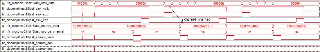
I have a two channel filter but have only been putting signals into channel 0. I have been debugging a DC block module. Eventually I decided there was a timing issue on the input (output of the FIR). With a bit of messing I found the signal appears on channel 1. Is this the same as what you are seeing? I have to make a few hardware modifications to my test boards before I can stuff a signal into channel 1. my dc block simulates ok. I use Altium Logic Analyser (which is the same as signal tap, i think). any advice? Quartus 9.2, 2 channel, decimating by 8, parrallel update- I have connected channel 0 and it seems that the output is swapped. That is, I is on channel 0 and Q is on channel 1, feeds the FIR. The output is Q channel 0 and I on channel 1. The actual filtering and data signals are fine. I have probably crossed my Is and Qs somewhere. I shall recheck the input to the FIR, but the output is definitly as above.- Mark as New
- Bookmark
- Subscribe
- Mute
- Subscribe to RSS Feed
- Permalink
- Report Inappropriate Content
I have checked and checked and the inputs to outputs are reversed
I with SOP & Valid, Q with EOP & Valid go in Q with SOP & Valid & Channel 0, I with EOP & Valid & Channel 1 comes out Anyone?- Mark as New
- Bookmark
- Subscribe
- Mute
- Subscribe to RSS Feed
- Permalink
- Report Inappropriate Content
I think I've had a similar issue with a multichannel CIC filter. 8 inputs between SOP and EOP and these appear in a jumbled (but in a constant) position at the outputs relative to the output EOP/SOP.
My problem was the thing generating the input data. There were some spurious DV's on the input, the first signal to enter the filter was an EOP rather than an SOP and the third packet had one DV too many between the SOP and EOP. Bad design on my part:oops:. I fixed these and problem dissappeared. I suspect it was the extra DV between SOP/EOP. Check your inputs carefully.
Reply
Topic Options
- Subscribe to RSS Feed
- Mark Topic as New
- Mark Topic as Read
- Float this Topic for Current User
- Bookmark
- Subscribe
- Printer Friendly Page