- Mark as New
- Bookmark
- Subscribe
- Mute
- Subscribe to RSS Feed
- Permalink
- Report Inappropriate Content
should i connect like a regular pin with assignment editor, one line for "I/O standard" and one line for "location" and that it, or i need to make another configurations?
i marked in the IP the "Disable dedicated Active Serial interface".
thanks
- Mark as New
- Bookmark
- Subscribe
- Mute
- Subscribe to RSS Feed
- Permalink
- Report Inappropriate Content
Hi Wolfgang,
Eventually I gave up!
I didn't 'tick' none of them, but I sill can see the signals in simulation through the hierarchy: "qspi_inf_inst/dedicated_interface".
About my other question, I saw that the REMOTE IP work on 20MHz max and my design (write/read) on much more, so I multiplexered clocks when the "select" is the "pof_error" signal so if the remote failed, I can write or read with the fast clock.
the quartus commented "19016 Clock multiplexers are found and protected".
all the others signals of the GFSI are multiplexered too.
Another problem is that the GFSI gives the data in burst of 32 bit while the REMOTE input is only 8 bit, so I needed to generate read pulse to the GFSI every 4 rounds of read request that came from the REMOTE and I send the data 8bit-8bit to the REMOTE.
but it worked, in the end.
thank you
Link Copied
- Mark as New
- Bookmark
- Subscribe
- Mute
- Subscribe to RSS Feed
- Permalink
- Report Inappropriate Content
Hi NAdel1,
Yes, your connection is right.
However, if you want to TICK "Disable dedicated Active Serial interface", I recommend you to TICK "Enable SPI pin interface" too. This will help you to convert atom pin to QSPI pin signal and this will make your life more easier.
Thanks
- Mark as New
- Bookmark
- Subscribe
- Mute
- Subscribe to RSS Feed
- Permalink
- Report Inappropriate Content
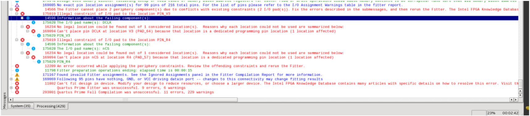
the problem is that when I TICK one of them or both I gen an error on the DCLK and nCS.
so my question is, what an I missing here?
another question, maybe there is connection, I have REMOTE IP too, I need the REMOTE to have access to the GFSI but I want access myself to write/read to the flash fpga configurations. so now I "export" al l the signals of the REMOTE IP and the GFSI IP, and I made mux outside the qsys module. is this the right way to do it?
- Mark as New
- Bookmark
- Subscribe
- Mute
- Subscribe to RSS Feed
- Permalink
- Report Inappropriate Content
Hi NAdel1,
May I know the status of this issue?
If you have any solution, you may share it to our community here.
Thanks
- Mark as New
- Bookmark
- Subscribe
- Mute
- Subscribe to RSS Feed
- Permalink
- Report Inappropriate Content
Hi Wolfgang,
Eventually I gave up!
I didn't 'tick' none of them, but I sill can see the signals in simulation through the hierarchy: "qspi_inf_inst/dedicated_interface".
About my other question, I saw that the REMOTE IP work on 20MHz max and my design (write/read) on much more, so I multiplexered clocks when the "select" is the "pof_error" signal so if the remote failed, I can write or read with the fast clock.
the quartus commented "19016 Clock multiplexers are found and protected".
all the others signals of the GFSI are multiplexered too.
Another problem is that the GFSI gives the data in burst of 32 bit while the REMOTE input is only 8 bit, so I needed to generate read pulse to the GFSI every 4 rounds of read request that came from the REMOTE and I send the data 8bit-8bit to the REMOTE.
but it worked, in the end.
thank you
- Mark as New
- Bookmark
- Subscribe
- Mute
- Subscribe to RSS Feed
- Permalink
- Report Inappropriate Content
Hi NAdel1,
I am glad to hear that the issue is resolved.
I'm apologize I can't help you much.
Thanks
- Subscribe to RSS Feed
- Mark Topic as New
- Mark Topic as Read
- Float this Topic for Current User
- Bookmark
- Subscribe
- Printer Friendly Page