- Mark as New
- Bookmark
- Subscribe
- Mute
- Subscribe to RSS Feed
- Permalink
- Report Inappropriate Content
Dear Sirs,
I did several tests using the de10-lite including using the files that come with the board. As I have no experience, I could not find out if the card is having problems or if I really am not able to describe the hardware correctly. Please, if someone can, send me a simple code that makes the writing and reading of a simple data in the SDRAM memory that exists on the board in verilog so that I can test its operation.
Sorry for my english !
Thanks, a lot for your help,
Marco
- Mark as New
- Bookmark
- Subscribe
- Mute
- Subscribe to RSS Feed
- Permalink
- Report Inappropriate Content
Hello Marco,
You need to check that your RTL code is correct before you solve the timing violation.
Any changes made to the RTL code could definitely affect the timing performance due to different routing.
Also, if you require help on timing, please post a new thread as this thread has a different root cause & solution.
Thank you,
Regards,
Nurina
Link Copied
- Mark as New
- Bookmark
- Subscribe
- Mute
- Subscribe to RSS Feed
- Permalink
- Report Inappropriate Content
Hello,
May I know which Quartus version you are using and which OS (Linux/Windows)?
Have you tried this example design? https://www.intel.com/content/www/us/en/design-example/715011/max-10-sdram-nios-test-max10-de10-lite.html
Here is an open sourced SDRAM example design: https://github.com/Arkowski24/sdram-controller
Regards,
Nurina
- Mark as New
- Bookmark
- Subscribe
- Mute
- Subscribe to RSS Feed
- Permalink
- Report Inappropriate Content
Hi Nurina,
Thanks for your help.!!!
I use quartus lite for windows version 20.1.0 build 711 and I don't know anything about us.
I'll check the version you uploaded from github.
Regards,
Marco
- Mark as New
- Bookmark
- Subscribe
- Mute
- Subscribe to RSS Feed
- Permalink
- Report Inappropriate Content
Hello Marco,
I’m glad that your question has been addressed, I now transition this thread to community support. If you have a new question, please login to https://supporttickets.intel.com , view details of the desire request, and post a feed/response within the next 15 days to allow me to continue to support you. After 15 days, this thread will be transitioned to community support. The community users will be able to help you on your follow-up questions.
p/s: If any answer from community or Intel support are helpful, please feel free to mark as solution, give Kudos and rate 4/5 survey
Regards,
Nurina
- Mark as New
- Bookmark
- Subscribe
- Mute
- Subscribe to RSS Feed
- Permalink
- Report Inappropriate Content
Hi Nurina,
Thanks a lot for your help and support.
I took the code in sent verilog and tried to use it to record more than one data in different addresses and when I read this data, the received data is different from the recorded data. I could not read the same recorded data
Regards,
Marco Gonzaga
- Mark as New
- Bookmark
- Subscribe
- Mute
- Subscribe to RSS Feed
- Permalink
- Report Inappropriate Content
Hello Marco,
How about this design example? https://www.intel.com/content/www/us/en/design-example/715013/max-10-sdram-rtl-test-max10-de10-lite.html?wapkw=de10%20lite%20sdram
It should work on Quartus Lite as well. Please let me know if you have any problems.
Regards,
Nurina
- Mark as New
- Bookmark
- Subscribe
- Mute
- Subscribe to RSS Feed
- Permalink
- Report Inappropriate Content
Hi Nurina,
As I informed you earlier, this project that you sent me is the same one that is on the CD that comes with the board and I couldn't write the data and read the data. I made some changes and it doesn't work as I informed you earlier.
For example, I would like to record 5 data in 5 different positions in memory and then read this data. I tried to test with this code example and it didn't work, I tried with other codes and it didn't work either. The code I'm testing now, I record a value and when I read it I get another one. If you want I can upload the code for you to check there in DE10.
Regards,
Marco
- Mark as New
- Bookmark
- Subscribe
- Mute
- Subscribe to RSS Feed
- Permalink
- Report Inappropriate Content
Hello Marco,
How did you test the code? Did you do it by simulation or signal tap?
Please send the .qar file. To generate this, go to Project>Archive Project.
Regards,
Nurina
- Mark as New
- Bookmark
- Subscribe
- Mute
- Subscribe to RSS Feed
- Permalink
- Report Inappropriate Content
Hello Nurina,
I'm testing the code directly on the DE10-Lite board.
I verified that the value that I write in the address 0 of the memory, is not written, even with a rewrite. The value that would be recorded at address 0 appears at address 1 and that of 1 appears at address 2. The data at address 3 is lost, which would actually be from address 2 and at address 3 the correct value appears and at 4 and 5 as well ... These reading and writing routines can be seen in the file vga_gm7123 lines 179 to 412.
I tried to comment a few lines in English to make it easier for you to understand.
I attached the file as you instructed. Thanks in advance for your support.
- Mark as New
- Bookmark
- Subscribe
- Mute
- Subscribe to RSS Feed
- Permalink
- Report Inappropriate Content
Hello Marco,
I would have to test this on Signal Tap to see what is possibly wrong.
Please allow some time while I investigate.
Regards,
Nurina
- Mark as New
- Bookmark
- Subscribe
- Mute
- Subscribe to RSS Feed
- Permalink
- Report Inappropriate Content
Hello Nurina,
No problem, I'm doing tests here too and if I can solve it let you know.
regards,
Marco
- Mark as New
- Bookmark
- Subscribe
- Mute
- Subscribe to RSS Feed
- Permalink
- Report Inappropriate Content
Hello Marco,
The project you sent has timing violation. Before you test your project on the board, you need to ensure that the RTL functionality and timing closure is met.
Why don't you try below example project first? I have compiled it and I don't see timing violation, and I expect that RTL functionality is met so you don't have to do more debugging on here:
Can you explain how you are testing the code?
Thanks,
Nurina
- Mark as New
- Bookmark
- Subscribe
- Mute
- Subscribe to RSS Feed
- Permalink
- Report Inappropriate Content
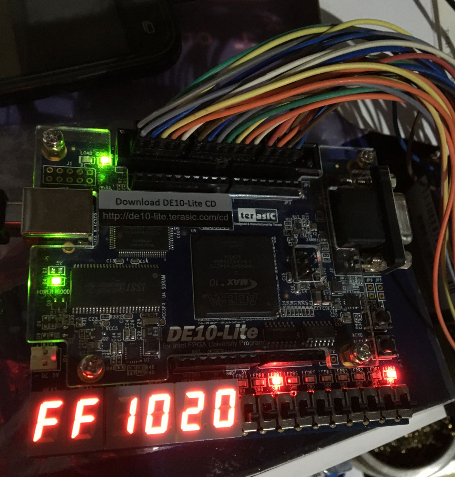
Hello Nurina,
The example from the link you sent me is the same one that I got from the cd that comes with the board, I got my functions and inserted them into the code and I don't know why it's having timing violation problems since I used the same example as the link that I used as a basis you sent me.
As I told you earlier I'm using the physical board for tests like the attached photo.
regards,
Marco
- Mark as New
- Bookmark
- Subscribe
- Mute
- Subscribe to RSS Feed
- Permalink
- Report Inappropriate Content
Hello Nurina,
After a new test, I did the following. I recorded the data from 0x00h to 0x0b as follows.
address 0x00h -> write value -> 0x05h -> value read -> 0xFFh ERROR !
address 0x01h -> write value -> 0x10h -> value read -> 0x10h CORRECT !
address 0x02h -> write value -> 0x20h -> value read -> 0x20h CORRECT !
address 0x03h -> write value -> 0x10h -> value read -> 0x10h CORRECT !
address 0x04h -> write value -> 0x20h -> value read -> 0x20h CORRECT !
address 0x05h -> write value -> 0xf8h -> value read -> 0xf8h CORRECT !
again repeat the values in the new memory address
address 0x06h -> write value -> 0x05h -> value read -> 0x05h CORRECT !
address 0x07h -> write value -> 0x10h -> value read -> 0x10h CORRECT !
address 0x08h -> write value -> 0x20h -> value read -> 0x20h CORRECT !
address 0x09h -> write value -> 0x10h -> value read -> 0x10h CORRECT !
address 0x0ah -> write value -> 0x20h -> value read -> 0x20h CORRECT !
address 0x0bh -> write value -> 0xf8h -> value read -> 0xf8h CORRECT !
see that from the address the recorded data is the same as the read data.
I don't know if timing could be causing this problem at the beginning of memory.
I'm starting to think that the memory may have some physical problem.
- Mark as New
- Bookmark
- Subscribe
- Mute
- Subscribe to RSS Feed
- Permalink
- Report Inappropriate Content
Hi Marco,
The timing violation is at the SDRAM. Since there is failure to read at the beginning, I believe there is problem in your RTL code. Please allow some time while I try check the RTL simulation on ModelSim.
Thanks,
Nurina
- Mark as New
- Bookmark
- Subscribe
- Mute
- Subscribe to RSS Feed
- Permalink
- Report Inappropriate Content
Hi Nurina,
Alright, I'll be waiting for you.
regards,
Marco Gonzaga
- Mark as New
- Bookmark
- Subscribe
- Mute
- Subscribe to RSS Feed
- Permalink
- Report Inappropriate Content
Hello Marco,
I have tried RTL simulation and it is not showing expected functionality.
You should check your code and do RTL simulation to find the root cause.
Regards,
Nurina
- Mark as New
- Bookmark
- Subscribe
- Mute
- Subscribe to RSS Feed
- Permalink
- Report Inappropriate Content
- Mark as New
- Bookmark
- Subscribe
- Mute
- Subscribe to RSS Feed
- Permalink
- Report Inappropriate Content
Hi Nurina,
Thank you for your time and your patience and help. at first I changed the ic and it's working. I will look at the rtl calmly to check for more problems but it is working.
Regards,
Marco
- Mark as New
- Bookmark
- Subscribe
- Mute
- Subscribe to RSS Feed
- Permalink
- Report Inappropriate Content
Hello Marco,
I'm glad to hear that your design is working.
If you are a beginner at RTL simulation, you may find this document useful: https://www.intel.com/content/www/us/en/docs/programmable/683248/18-0/simulation-quick-start.html
With that, I now transition this thread to community support. If you have a new question, please login to https://supporttickets.intel.com , view details of the desire request, and post a feed/response within the next 15 days to allow me to continue to support you. After 15 days, this thread will be transitioned to community support. The community users will be able to help you on your follow-up questions.
p/s: If any answer from community or Intel support are helpful, please feel free to mark as solution, give Kudos and rate 4/5 survey
Regards,
Nurina
- Mark as New
- Bookmark
- Subscribe
- Mute
- Subscribe to RSS Feed
- Permalink
- Report Inappropriate Content
Hi Nurina,
I would like you to help me solve the timing problems as well so I would have the project completely without any errors. I don't know how to do that or get it right in Quartus.
regards,
Marco
- Subscribe to RSS Feed
- Mark Topic as New
- Mark Topic as Read
- Float this Topic for Current User
- Bookmark
- Subscribe
- Printer Friendly Page