- Mark as New
- Bookmark
- Subscribe
- Mute
- Subscribe to RSS Feed
- Permalink
- Report Inappropriate Content
Hi,
I’m using the Cyclone V E FPGA Development Kit and I’m trying to program the EPCQ using the AS (Active Serial) configuration.
I did the following steps:
- I correctly configured the MSEL pins (following the instruction of the “Cyclone V device handbook”)
- I removed the R16 and R22 0 ohm resistors (and put them on R18 and R23) (see the “Attach_1.png” image)
- I generated the .jic file (see the “Attach_2.png” image)
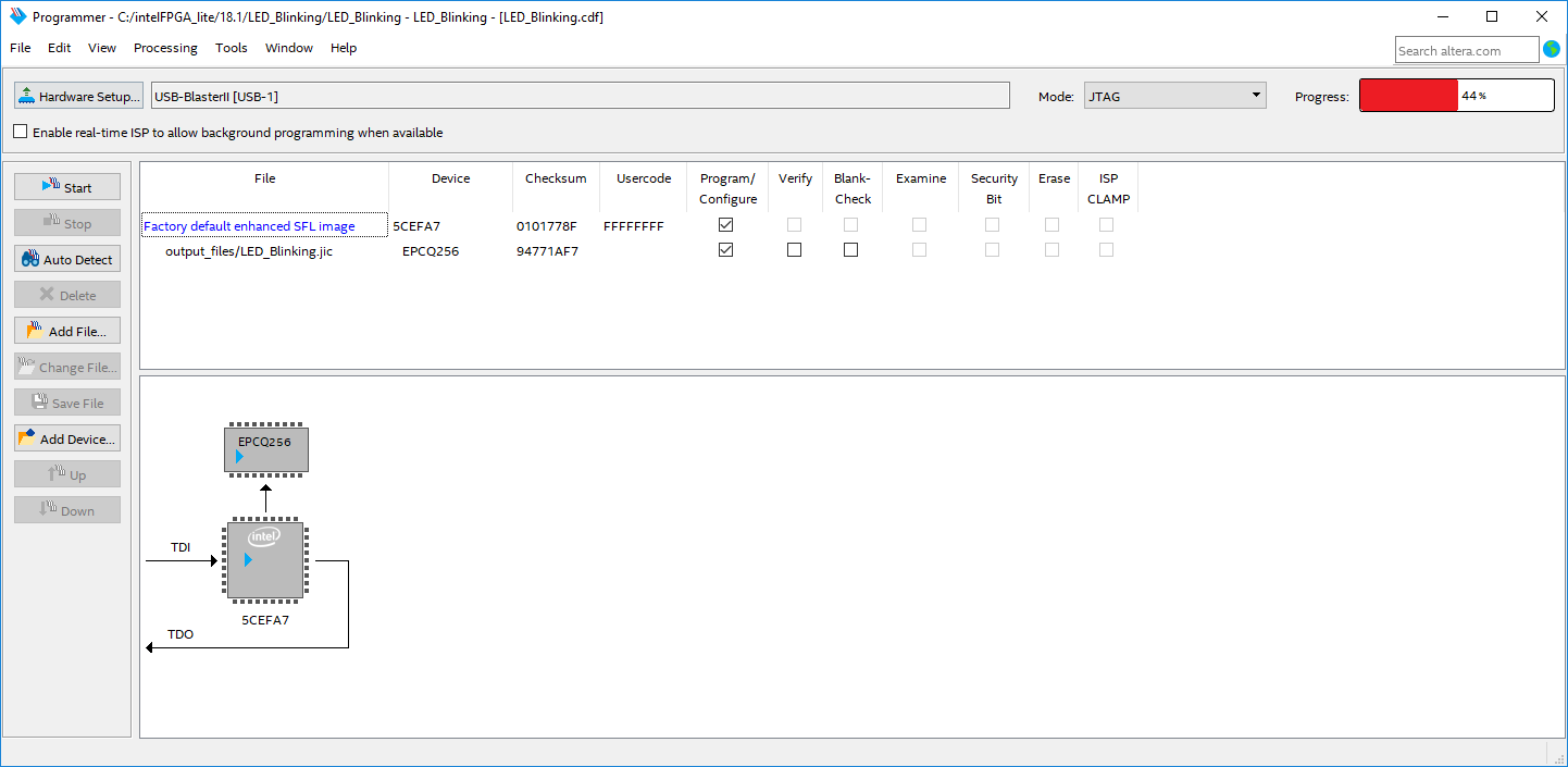
But in the “Program device” window, when I try to load the .jig file into the EPCQ, I obtain a failure in the progress bar (see “Attach_3.png”).
My question is: is it possible to program the EPCQ bypassing the MAX V present on the board (I’m quite sure is possible). If so, why can’t I program it correctly?
Link Copied
- Mark as New
- Bookmark
- Subscribe
- Mute
- Subscribe to RSS Feed
- Permalink
- Report Inappropriate Content
Hi DGiar,
What is the error message when the Quartus programmer failed to program the EPCQ256 (progress bar failed at 44%)? In the Quartus message log, you should be able to see the error message. You can perform auto-detect operation with the Quartus programmer to detect if the JTAG chain contain a single device (Cyclone V) or multiple devices (Cyclone V + MAX V). If the Quartus programmer only detect Cyclone V then the MAX V should already bypassed.
Regards,
Nooraini
- Mark as New
- Bookmark
- Subscribe
- Mute
- Subscribe to RSS Feed
- Permalink
- Report Inappropriate Content
Hi, thank you for your answer.
The error message is the following:
“Error (209025): Can't recognize silicon ID for device 1. A device's silicon ID is different from its JTAG ID. Verify that all cables are securely connected, select a different device, or check the power on the target system. Make sure the device pins are connected and configured correctly.”
The point is that I can program the FPGA with the .sof file correctly (see “Screen1”), while I cannot program the EPCQ with the .jic file (see “Screen2.png”): I noticed that in the first case the Device Name is 5CEFA7F31, while in the second case the Device Name is only 5CEFA7 and I cannot change it.
Also, when I generate the .jic file I cannot select the 5CEFA7F31 (see “Screen3.png”).
Hope that this help, thank you in advance.
- Mark as New
- Bookmark
- Subscribe
- Mute
- Subscribe to RSS Feed
- Permalink
- Report Inappropriate Content
Hi DGiar,
Since you are using USB Blaster II cable, can you try to reduce the USB Blaster II TCK value to either 16Mhz or lower? By default, the frequency for the USB-Blaster II download cable is 24MHz. For the steps to change the USB Blaster II TCK value, please refer to the following KDB link:
Once you have change the TCK value, please try to program the .jic file if this help to fix the issue.
Regards,
Nooraini
- Mark as New
- Bookmark
- Subscribe
- Mute
- Subscribe to RSS Feed
- Permalink
- Report Inappropriate Content
Hi, unfortunately I don't have the USB Blaster II cable (since there isn't in the Cyclone V E Dev Kit).
To program the FPGA I'm using the USB type B cable through the JTAG interface.
Is there any possibility to do it anyway?
- Mark as New
- Bookmark
- Subscribe
- Mute
- Subscribe to RSS Feed
- Permalink
- Report Inappropriate Content
Hi DGiar,
The Cyclone V E Dev Kit is built with on-board USB Blaster II type B. Even in the screen shot that you provided before was showing that Quartus programmer was using USB Blaster II to program the .jic file. You can refer to the attached screen shot that I have include a snippet of the Cyclone V E Dev Kit Reference Manual which mentioned on-board USB Blaster II type B.
Thus, please try to reduce the USB Blaster II TCK value to either 16Mhz or lower. For the steps to change the USB Blaster II TCK value, please refer to the following KDB link:
Once you have change the TCK value, please try to program the .jic file if this help to fix the issue.
Regards,
Nooraini
.png)
- Mark as New
- Bookmark
- Subscribe
- Mute
- Subscribe to RSS Feed
- Permalink
- Report Inappropriate Content
Hi Nooraini,
thank you for your answer.
I tried to do what you said and I obtained the following:
- With 24 MHz clock the progress bar stops at 44%
- With 12 MHz clock the progress bar stops at 58%
- With 6 MHz, 3 MHz and 2 MHz (and so on) clocks the progress bar stops at 73%.
Sorry for asking you again, but do you have any tips for solving this?
Thank you in advance.
Regards.
- Mark as New
- Bookmark
- Subscribe
- Mute
- Subscribe to RSS Feed
- Permalink
- Report Inappropriate Content
Hi DGiar,
Did you set the MSEL 4,2,1,0 pins to AS mode? At dip SW1 you are require to set the MSEL pins according to the correct configuration scheme. Thus you need to set the SW1 either to 1011 or 1010. You can refer to the attached screen shot. We have a Cyclone V E dev kit that I can program the .jic file successfully.
Regards,
Nooraini
- Mark as New
- Bookmark
- Subscribe
- Mute
- Subscribe to RSS Feed
- Permalink
- Report Inappropriate Content
Hi Nooraini,
thank you.
The configuration of the MSEL pins was already done (see the first post).
But the error is always the same:
“Error (209025): Can't recognize silicon ID for device 1. A device's silicon ID is different from its JTAG ID. Verify that all cables are securely connected, select a different device, or check the power on the target system. Make sure the device pins are connected and configured correctly.”
Any idea?
Thank you in advance for your help!
Regards,
Diego
- Mark as New
- Bookmark
- Subscribe
- Mute
- Subscribe to RSS Feed
- Permalink
- Report Inappropriate Content
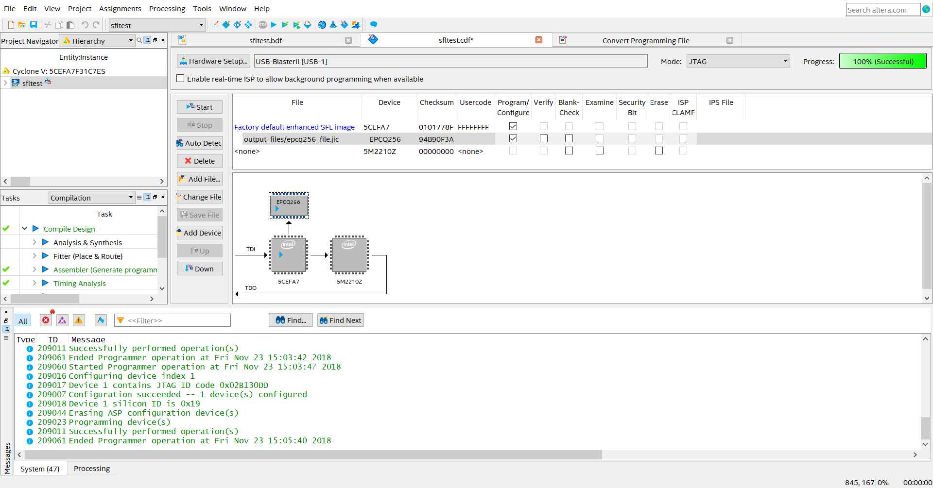
Hi Diego,
Did you try to erase the MAX V contents first? Before programming the .jic file, first I would erase the MAX V contents. Then ensure the MSEL pins (dip SW1) is set for AS mode. When program the .jic file, I can see the programmer can successfully detect the EPCQ256 ID (0x19) and continue to perform erase and program operation.
Regards,
Nooraini
- Subscribe to RSS Feed
- Mark Topic as New
- Mark Topic as Read
- Float this Topic for Current User
- Bookmark
- Subscribe
- Printer Friendly Page