- Mark as New
- Bookmark
- Subscribe
- Mute
- Subscribe to RSS Feed
- Permalink
- Report Inappropriate Content
I am new to programming FPGA's in VHDL. One of my starter projects is to write VHDL that will receive a SPI message from my Raspberry Pi, that will then produce a PWM with the duty cycle set from the SPI message. For instance, the PI may send a 25, and the FPGA will create a PWM with 25% duty cycle. I am using this code to create the SPI slave portion of code
https://www.digikey.com/eewiki/pages/viewpage.action?pageId=7569477
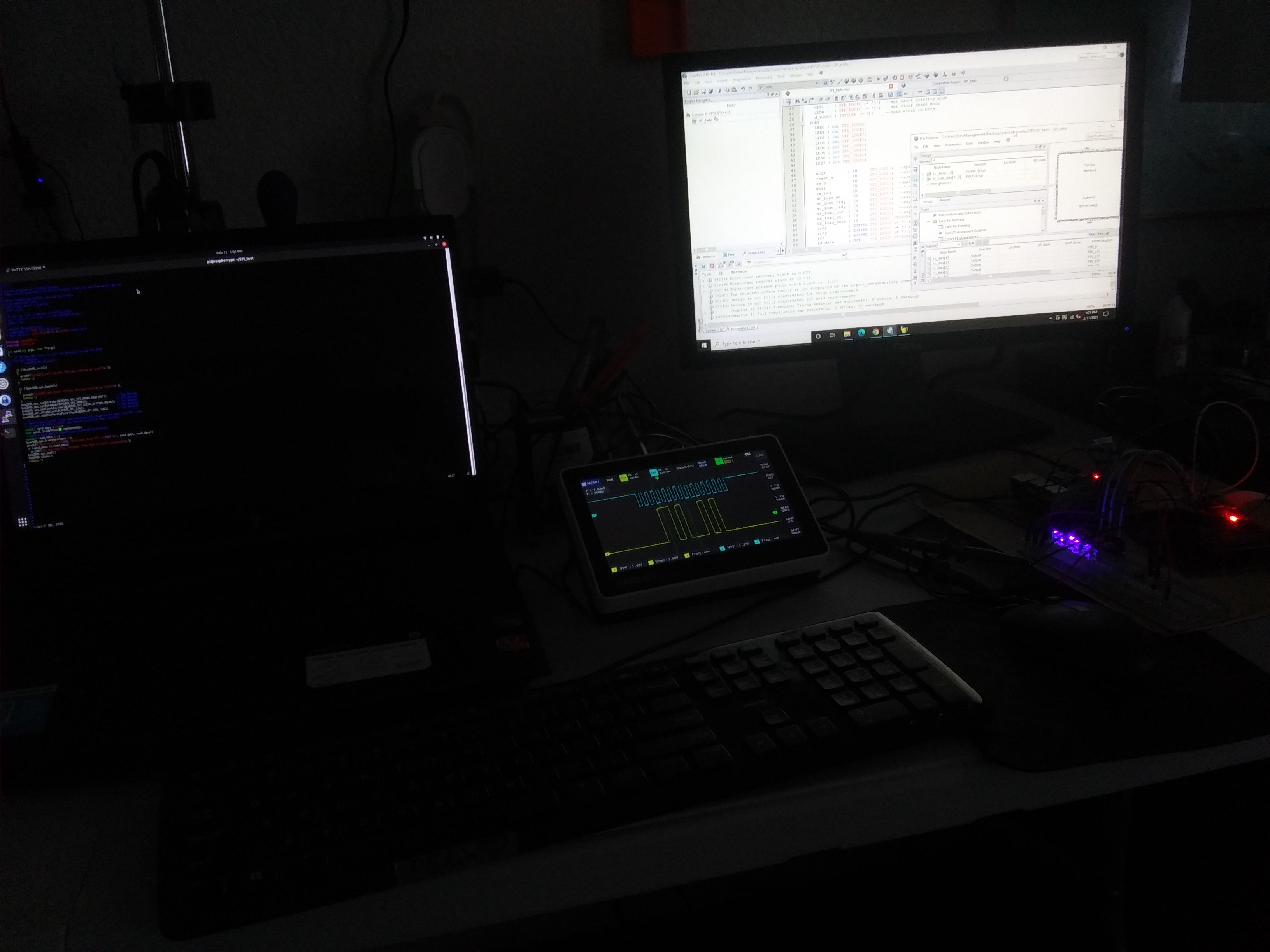
My debug methods include LED's, lighting up the byte value when received. I also have an oscilloscope to try and verify the PI is sending the message, and that the clock is being correctly read by the FPGA. I am including a picture of my setup.
Is there a better way to watch the ports and the signals, because this method does not seem optimal and I think it is due to my not knowing what to do. It's not working, the rx_data vector does not give very stable results. One thing I found that I think is helping is connecting the Raspberry Pi ground to the FPGA ground.
Any advice is greatly appreciated, I feel I am kind of floundering. My goal is to eventually create a DMA as is used in the labview environment, which is where I first used an FPGA. I was able to create a PWM as was found here
https://www.digikey.com/eewiki/pages/viewpage.action?pageId=20939345
Link Copied
- Mark as New
- Bookmark
- Subscribe
- Mute
- Subscribe to RSS Feed
- Permalink
- Report Inappropriate Content
I am working to develop a larger project, making BMS and other useful electronic controls with low cost parts. My goal is to control a buck-boost board like may be used in regenerative braking or other green energy projects. Of course, this is just 1 piece of a larger puzzle, you can see here
https://codeandbuildit.com/2021/02/11/fpga-buck-boost-02-07-2021-spi-with-fpga/
I have a lot of work to do, hoping to get through this learning curve ASAP, which is kind of hard without the funding, technical ability, etc... but, each step 1 at a time
- Mark as New
- Bookmark
- Subscribe
- Mute
- Subscribe to RSS Feed
- Permalink
- Report Inappropriate Content
Just a quick update. I have figured out to use the Signal Tap II Digital Analyzer provided on Quartus II. I now receive SPI messages, and produce a PWM output based on received message. I would like to learn more about boundary scans, creating DMA like labview does with their single board RTOS
https://zone.ni.com/reference/en-XX/help/371599P-01/lvfpgaconcepts/fpga_dma_how_it_works/
and to start will look into a ADC to gather data now. I am very interested in the NIOS II, and the long road ahead as I continue learning better techniques including multimedia and RF comm..
https://codeandbuildit.com/2021/02/26/fpga-buck-boost-02-11-2021-qml-controlling-fpga/
I thank you for providing a great learning material (Cyclone II - <$30) at a price I can afford
- Subscribe to RSS Feed
- Mark Topic as New
- Mark Topic as Read
- Float this Topic for Current User
- Bookmark
- Subscribe
- Printer Friendly Page