- Mark as New
- Bookmark
- Subscribe
- Mute
- Subscribe to RSS Feed
- Permalink
- Report Inappropriate Content
Hi
I am trying to make a design using the video_sync_generator component on a de2-70 board, but i am getting strange results. For testing purposes,i connected the tree color component(Red,Green and Blue) to Vcc,so i expected to get a nice white screen but the screen is all black.The synchronization signals (VS and HS ) seem ok (the screen correctly detect the resolution). I joint a picture of my connection , if anyone have an idea or ran onto the same problem Thanks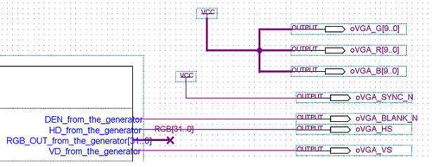
Link Copied
4 Replies
- Mark as New
- Bookmark
- Subscribe
- Mute
- Subscribe to RSS Feed
- Permalink
- Report Inappropriate Content
Hi.
Don´t connect the R,G,B to Vcc, instead assign a value to them, while the scan time is the correct. Speaking about H signal, it is after H blanking, and before the next H blank pulse. Regards. Alberto.- Mark as New
- Bookmark
- Subscribe
- Mute
- Subscribe to RSS Feed
- Permalink
- Report Inappropriate Content
If you'd like a very simple example of video sync generation take a look at
http://repo.or.cz/w/yari.git?a=blob;f=rtl/target/de2-70/video.v;h=ea843e589cae2a047d56537b656d704c31e68597;hb=head This is a complete video interface for the DE2-70 minus the memory controller. This is part of YARI (http://thorn.ws/yari) I don't think the sync generation could be implemented much simpler. Tommy- Mark as New
- Bookmark
- Subscribe
- Mute
- Subscribe to RSS Feed
- Permalink
- Report Inappropriate Content
--- Quote Start --- Hi. Don´t connect the R,G,B to Vcc, instead assign a value to them, while the scan time is the correct. Speaking about H signal, it is after H blanking, and before the next H blank pulse. Regards. Alberto. --- Quote End --- Hi i am not sure to follow the "assign a value while the scan time is correct" part .My design is not using any .verilog (or vhdl ) file , all is done in a schematic file. Still for investigating , i modify the video_sync_generator.v file and redirect the output.Instead of having the output RGB_OUT connected to the data_input, , i directly assigned a constant to the output signal but i still get a black screen instead of a white screen Thanks
- Mark as New
- Bookmark
- Subscribe
- Mute
- Subscribe to RSS Feed
- Permalink
- Report Inappropriate Content
Hi.
Why not to add an inverter between the oVGA_BLANK_N and the RGB data, and then open them from Vcc. Or did you tried leaving the 9th bit of RGB data to GND instead VCC. or did you tried with only one colour ?
Reply
Topic Options
- Subscribe to RSS Feed
- Mark Topic as New
- Mark Topic as Read
- Float this Topic for Current User
- Bookmark
- Subscribe
- Printer Friendly Page