- Mark as New
- Bookmark
- Subscribe
- Mute
- Subscribe to RSS Feed
- Permalink
- Report Inappropriate Content
Thank you for being here to help me.
I am confusing between the WORDS and SYMBOLS address units in Quartus Platform designer.
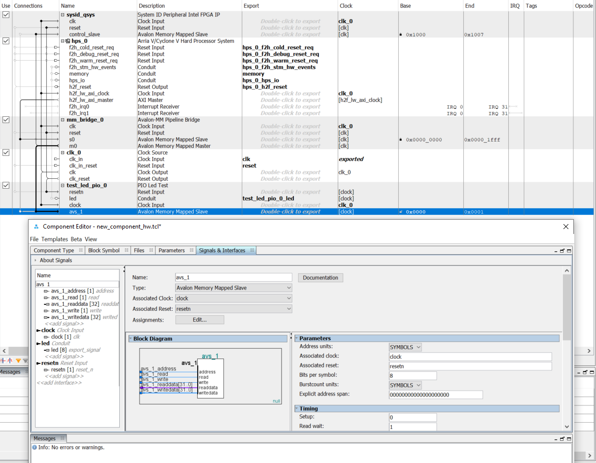
I am designing a module that receives data from cpu and outputs that data to 8 leds (similar to a PIO core). I implemented an avalon memory-mapped slave interface having data width = 32 bits, 1 address line as shown in the pictures below. By default, it is set to 8 bits per symbol.
+ As I choose SYMBOLS address units and assign base address (0x00) for the slave, the end address is 0x01. (Picture 1)
+ As I choose WORDS address units, keep the same base address 0x00, the end address is 0x07. (Picture 2).
Please help me explain the difference between the two address units.
Link Copied
- Mark as New
- Bookmark
- Subscribe
- Mute
- Subscribe to RSS Feed
- Permalink
- Report Inappropriate Content
I'll preface this response with the fact that in my reply, using inclusive language, host=master and agent=slave.
By default in Platform Designer (PD), agents (like the IP included in the IP catalog) use word addressing (your picture 2) based on the width of the data bus. With a single address bit like in your design, that means your design has 2, 32-bit registers, a total of 8 bytes. Thus, a host, which by default uses byte addressing (8-bit symbols), can access your agent at any value from 0x0 to 0x7, though the PD interconnect will obviously only present the single bit address to the agent (0x0 or 0x1). The end address column always shows the end address for how a host would access the agent, but the interconnect can translate the address as needed. The address that a host would issue would depend on the address bus on the host side. If it was 4 bits, for example, the host would issue 0x0 to get the first 32-bit word/register of your component and 0x3 to access the second 32-bit word/register.
Switching the address units to symbol and then setting it to 8 bits per symbol, since you only have a single address bit, the 8 bits per symbol option is basically being ignored. So a host would access the two 32-bit registers at either address location 0 or 1 as indicated in the base and end address columns of picture 1. If you had more address bits (at least 3), the end address in picture 1 would look more like it does in picture 2.
Let me know if this is clear or not.
- Subscribe to RSS Feed
- Mark Topic as New
- Mark Topic as Read
- Float this Topic for Current User
- Bookmark
- Subscribe
- Printer Friendly Page