- Mark as New
- Bookmark
- Subscribe
- Mute
- Subscribe to RSS Feed
- Permalink
- Report Inappropriate Content
Dear Community,
We are facing a critical issue in implementing a design using a Cyclone 10 LP with a pwm generator logic driving a LVDS pin.
The resolution of the output logic is 1ns (1 Ghz delay-chain clock), however the counter clock is 125Mhz and thus maximum possible togglig frequency of the output is 62Mhz.
This has proven to be reliable and working well during development using single ended TTL outputs, however the actual implementation requires the outputs to be LVDS.
Quartus 20.1.0 B711 however reports the toggle rate of the pin to be 1GHz (which is out of spec) and thus fails the fitter operation. (Error 176060)
I have tried to specify both I/O Maximum Toggle Rate as well as Power Toggle Rate for the affected pins to be the real 62.5MHz as well as 0Mhz in the Assignment Editor without any effect.
Is there any other way to force Quartus to accept the correct maximum toggle rate by specifying it via sdc, assignment, vhdl? Is it possible to ignore the check alltogether?
Thank you,
Chris
Link Copied
- Mark as New
- Bookmark
- Subscribe
- Mute
- Subscribe to RSS Feed
- Permalink
- Report Inappropriate Content
The datasheet LVDS TX Datarate shows that it cannot go up to 1Gbps.

When you say: This has proven to be reliable and working well during development using single ended TTL outputs...do you mean you are able to implement this in actual board at 1Gbps datarate?
- Mark as New
- Bookmark
- Subscribe
- Mute
- Subscribe to RSS Feed
- Permalink
- Report Inappropriate Content
Yes and no:
Implement reliably on a board: Yes, on the Intel EK-10CL025U256
1Gbps data rate: Yes & No: The edge position resolution is 1ns (thus information is transmitted technically with 1Gbps), however the pin can only toggle with at most 62.5MHz as it is impossible for the coounter to reset in less than 16 cycles with the output going high at least once per period.
It is possible to toggle the pin high or for a single cycle, which results in a well defined output signal with a clean signal, that is eighter high or low for only 1ns, but not both, the period is at least 16 cycles.
In essence, the transition edges are positioned using 1GHz clock, the square signal however toggles with max. 62.5Mhz. Should glitches occur when the on/off times are lower than 2ns, this is perfectly acceptable since all the driven external circuitry would recognize this as noise and ignore it entirely anyway.
Edit: During development i managed to test also toggle rates on TTL pins that were according to the design limits not capable of toggle rates of over 500MHz (and in case quartus detected it based on the logic used to drive the pin, rejected with a similar error; For that experiment i could afford extra locic, so i used secondary inputs that i then tied to VCC to trick quartus into thinking the pin would not toggle at that rate - this is no longer an option as the final implementation does not allow for any extra delays before the output.) at up to 1.3GHz and the output signal was still well enough defined for what we need. This may well be a reliability topic and may cause other potentially unexpected behaviour, however it it would be nice to at least be possible to bypass the error, as the device is clearly capable of operating in those conditions.
- Mark as New
- Bookmark
- Subscribe
- Mute
- Subscribe to RSS Feed
- Permalink
- Report Inappropriate Content
Hi Chris,
Could you attach a simplified design that shows the error?
- Mark as New
- Bookmark
- Subscribe
- Mute
- Subscribe to RSS Feed
- Permalink
- Report Inappropriate Content
Yes, give me a few hours. I am working on a test program for this issue at the moment. I will attempt to modify it so it reflects the real application as close as possible.
- Mark as New
- Bookmark
- Subscribe
- Mute
- Subscribe to RSS Feed
- Permalink
- Report Inappropriate Content
@JonWay_C_Intel I have created and attached two configurations of a example project configured to run on the Intel Cyclone 10 LP Evaluation Kit.
one configuration showing the error message, and one showing that the settings rejected by quartus are valid (using on the fly reconfiguration to allow compliation with lower clock speed).
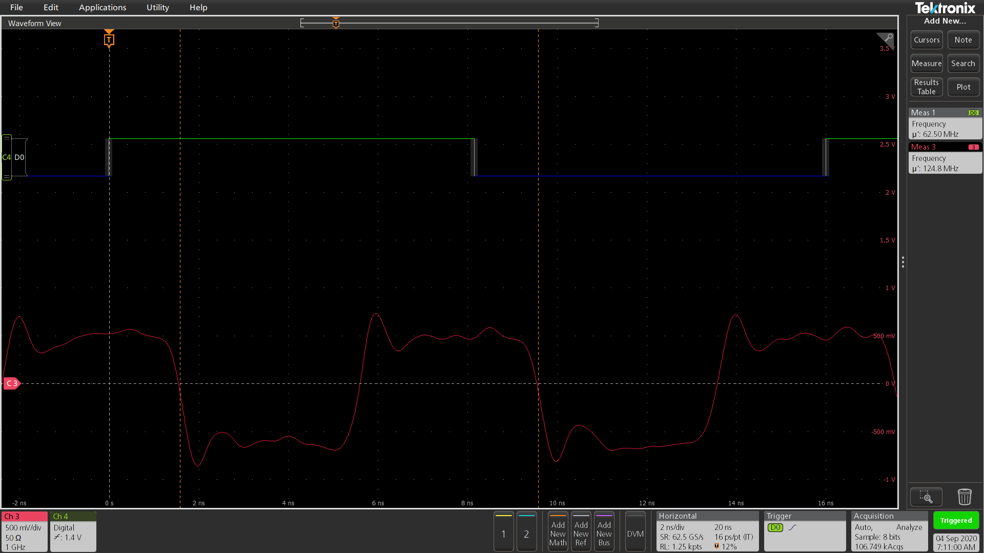
The example contains a description on how it is constructed and how to connect it as well as the resulting output waveforms.
Materials required:
EK-10CL025U256
Oscilloscope with >= 1Ghz bandwith & differential probe, 100 Ohm LVDS termination resistor, + 1 Single ended probe
Quartus Prime 20.1.0 Build 771 06/05/2020 SJ Lite Edition
Thank you for your support,
Chris
- Mark as New
- Bookmark
- Subscribe
- Mute
- Subscribe to RSS Feed
- Permalink
- Report Inappropriate Content
Thanks for the design. I have a better idea now. You are trying to make a GPIO IO standard LVDS to toggle at 1GHz. It will message: Error (176060): The transmitter driving I/O pin pin_arduinobus_j7_4 at data rate 1000 Mbps exceeds the maximum allowed data rate of 740 Mbps for LVDS output
This is expected as the datasheet stated:

- Tags:
- H
- Mark as New
- Bookmark
- Subscribe
- Mute
- Subscribe to RSS Feed
- Permalink
- Report Inappropriate Content
@JonWay_C_Intel i was providing an example of the issue as you had requested in the simplest form possible. It was intended to show the error encountered, not the real application as this is a public forum and i cannot disclose the company's intellectual property in this manner.
To clarify: this error persists, independent of the toggle rate of the pin, as it is an issue with the quartus software deriving the real toggle rate and has nothing to do with the datasheet specification. To highlight this i have modified the example to a division factor of 4, now delivering instead of 500Mhz (=1Gbps) as before an output rate of 250MHz (=500Mbps) which is well within the datasheet specification. You can modify this to any arbitrary division factor, the issue will persist no matter how low you make the toggle rate of the pin:

I have attached the modified examples:
1) version failing during the fitting process "correct implementation of the PLL parameters"
2) successfully compilable "dynamic pll workaround"
These represent the equivalent counterparts to the previous examples:
1) "Config_TestProgram - Not working (1GHz PLL intitial)" (08-28-2020 01:06 PM)
2) "Config_TestProgram - Working (500MHz PLL initial)" (08-28-2020 01:06 PM)
If you wish to have a look to the actual application causing this problem, please provide me a means to contact you in a non-public fashion to exchange the data and / or arrange the potential shipment of the demonstation hardware.
Thank you,
-Chris
- Mark as New
- Bookmark
- Subscribe
- Mute
- Subscribe to RSS Feed
- Permalink
- Report Inappropriate Content
@JonWay_C_Intel i was providing an example of the issue as you had requested in the simplest form possible. It was intended to show the error encountered, not the real application as this is a public forum and i cannot disclose the companys intellectual property in this manner.
To clarify: this error persists, independent of the toggle rate of the pin, as it is an issue with the quartus software deriving the real toggle rate and has nothing to do with the datasheet specification. To highlight this i have modified the example to a division factor of 4, now delivering instead of 500Mhz (=1Gbps) as before an output rate of 250MHz (=500Mbps) which is well within the datasheet specification. You can modify this to any arbitrary division factor, the issue will persist no matter how low you make the toggle rate of the pin:

I have attached the modified examples:
1) version failing during the fitting process "correct implementation of the PLL parameters"
2) successfully compilable "dynamic pll workaround"
These represent the equivalent counterparts to the previous examples:
1) "Config_TestProgram - Not working (1GHz PLL intitial)" (08-28-2020 01:06 PM)
2) "Config_TestProgram - Working (500MHz PLL initial)" (08-28-2020 01:06 PM)
If you wish to have a look to the actual application causing this problem, please provide me a means to contact you in a non-public fashion to exchange the data and / or arrange the potential shipment of the demonstation hardware.
Thank you,
-Chris
- Mark as New
- Bookmark
- Subscribe
- Mute
- Subscribe to RSS Feed
- Permalink
- Report Inappropriate Content
- Mark as New
- Bookmark
- Subscribe
- Mute
- Subscribe to RSS Feed
- Permalink
- Report Inappropriate Content
@JonWay_C_Intel i was providing an example of the issue as you had requested in the simplest form possible. It was intended to show the error encountered, not the real application as this is a public forum and i cannot disclose the company's intellectual property in this manner.
To clarify: this error persists, independent of the toggle rate of the pin, as it is an issue with the quartus software deriving the real toggle rate and has nothing to do with the datasheet specification. To highlight this i have modified the example to a division factor of 4, now delivering instead of 500Mhz (=1Gbps) as before an output rate of 250MHz (=500Mbps) which is well within the datasheet specification. You can modify this to any arbitrary division factor, the issue will persist no matter how low you make the toggle rate of the pin:

I have attached the modified examples:
1) version failing during the fitting process "correct implementation of the PLL parameters"
2) successfully compilable "dynamic pll workaround"
These represent the equivalent counterparts to the previous examples:
1) "Config_TestProgram - Not working (1GHz PLL intitial)" (08-28-2020 01:06 PM)
2) "Config_TestProgram - Working (500MHz PLL initial)" (08-28-2020 01:06 PM)
If you wish to have a look to the actual application causing this problem, please provide me a means to contact you in a non-public fashion to exchange the data and / or arrange the potential shipment of the demonstation hardware.
Thank you,
-Chris
P.S.: My appologies for the many posts/edits of this message - something went wrong while updating it to correct a spelling mistake and the post disappeared...
- Mark as New
- Bookmark
- Subscribe
- Mute
- Subscribe to RSS Feed
- Permalink
- Report Inappropriate Content
- Mark as New
- Bookmark
- Subscribe
- Mute
- Subscribe to RSS Feed
- Permalink
- Report Inappropriate Content
Thanks @chris_notsch for clarifying the issue. The problem statement is: PLL output clock 1Ghz is divided down by internal logics to 500Mhz at the output pin (set as LVDS IO Standard). Despite not toggling at 1Ghz, why did it complain that it is (thus causing an error of exceeding the maximum rate)?
I am checking on it and will get back to you as soon as i have an update. Thanks.
- Mark as New
- Bookmark
- Subscribe
- Mute
- Subscribe to RSS Feed
- Permalink
- Report Inappropriate Content
The pll reconfiguration can be used as workaround for now. As for the timing violations related to pll reconfiguration, you may file a new forum case so that the subject matter expert can work on it with you.
- Subscribe to RSS Feed
- Mark Topic as New
- Mark Topic as Read
- Float this Topic for Current User
- Bookmark
- Subscribe
- Printer Friendly Page