- 新着としてマーク
- ブックマーク
- 購読
- ミュート
- RSS フィードを購読する
- ハイライト
- 印刷
- 不適切なコンテンツを報告
Hi all,
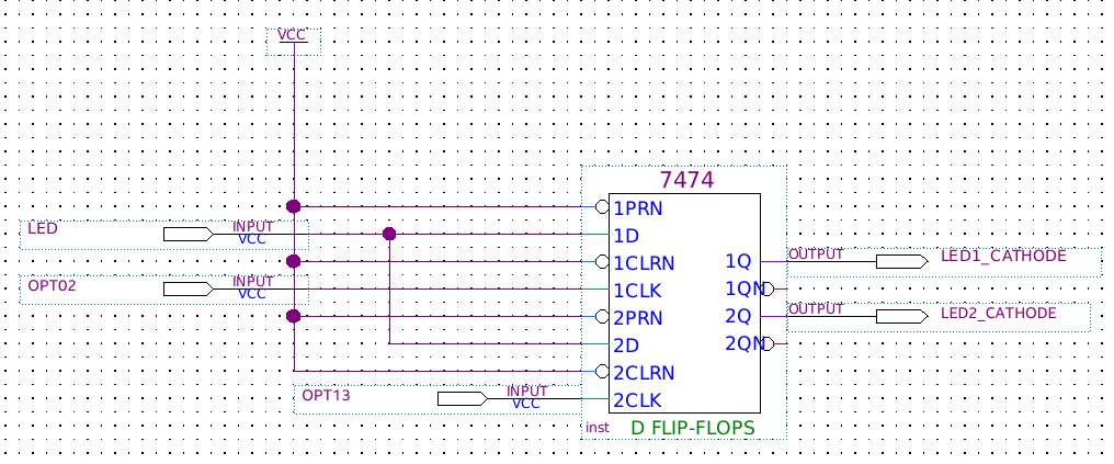
I'm trying to implementing under Quartus this simple LED circuit (based on two D flip-flops) using a +5V CPLD (EPM7032)

As you can see, there are only three signals inputs to the flip-flops :
-LED which can be fixed HIGH or LOW
-CLK1 that can be fixed HIGH or asserted (duration is 2.5us)
-CLK2 that can be fixed HIGH or asserted (duration is 2.5us)
When LED signal is low and CLK1 (or CLK2) is asserted the not negated output goes LOW activating the LED which start to blink (I use LEDs with built-in oscillator).
Well, the circuit works well with TTL gates (74LS74 or 74HC74) but when I implement it under Quartus 12.1it does not work well because, when the only CLK2 is asserted and LED2 blinks, also LED1 starts to blink.Here's the Quartus schematics :

Which could be the problem?Perhaps I have to turn off some of the Quartus compiler settings (like Auto Global Clock).Thanks in advance for any help or advice.
コピーされたリンク
- 新着としてマーク
- ブックマーク
- 購読
- ミュート
- RSS フィードを購読する
- ハイライト
- 印刷
- 不適切なコンテンツを報告
What are OPT0/2 and OPT1/3 connected to for clocking?
Also, in an FPGA, this is not a typical design. Normally you would just use a D flip-flop primitive or write code (Verilog or VHDL) to implement it. I don't know if that has any affect, but it's something to consider.
- 新着としてマーク
- ブックマーク
- 購読
- ミュート
- RSS フィードを購読する
- ハイライト
- 印刷
- 不適切なコンテンツを報告
Hi,
The functionality of the Megafunction tested with no problem check the image attached.
While OPT02 is asserted, LED1_CATHODE will toggle. As OPT13 is not asserted, LED2_CATHODE will not toggle.
Thanks,
Best regards,
Sheng
p/s: If any answer from the community or Intel Support are helpful, please feel free to give best answer or rate 4/5 survey.
- 新着としてマーク
- ブックマーク
- 購読
- ミュート
- RSS フィードを購読する
- ハイライト
- 印刷
- 不適切なコンテンツを報告
Thanks for reply.The problem is that, when the only OPT13 is asserted both LEDs toggle while only LED2_CATHODE should actually toggle.
P.S.
OPT02 and OPT13 are coming from an old japanese computer.
- 新着としてマーク
- ブックマーク
- 購読
- ミュート
- RSS フィードを購読する
- ハイライト
- 印刷
- 不適切なコンテンツを報告
I see.
Anyway, OPT01 and OPT13 are active LOW signal so, normally they are fixed HIGH and then get asserted to LOW for 2.5us.As well as, LED_CATHODE1 and LED_CATHODE2 shoud be fixed HIGH so that the LEDs will not blink because both anodes are wired to +5V thru 220 Ohm resistors.Therefore, the LEDs should blink only when LED_CATHODE1 and LED_CATHODE2 toggle to LOW.
- 新着としてマーク
- ブックマーク
- 購読
- ミュート
- RSS フィードを購読する
- ハイライト
- 印刷
- 不適切なコンテンツを報告
These are positive edge-triggered flip-flops so the fact that the "clocks" are normally held high is not going to give you accurate behavior. Perhaps you should be using the /Q outputs instead.
- 新着としてマーク
- ブックマーク
- 購読
- ミュート
- RSS フィードを購読する
- ハイライト
- 印刷
- 不適切なコンテンツを報告
Hi,
Do you have any further update or concern?
Thanks,
Best regards,
Sheng