- Mark as New
- Bookmark
- Subscribe
- Mute
- Subscribe to RSS Feed
- Permalink
- Report Inappropriate Content
Hello,
I am working on a simple state machine but for some reason the output value is not assigned correctly. First it is supposed to go into state init and assign default values to my 4x8bit internal signals (key_int), then should go to state assign to assign and combine the internal signals into 1x32bit output signal (key). And that is where it fails. When I run my test bench it always shows that key="00000000000000000000000000000000". Although key_int(0..3) are set to x"61" during the init phase. I already placed a counter in both states so I don't get a timing problem. I also replace the array with 4x std_logic_vector signals and assiged those during init with the same result. Surpringly: when I assign key directly in init it takes it. What am I doing wrong here? Btw I am using Quartus II 15.0.0. if that makes any difference.use ieee.std_logic_1164.all;
use ieee.std_logic_unsigned.all;
use ieee.numeric_std.all;
entity buttonToKey is port(
clk_50 : in std_logic;
button : in std_logic_vector(5 downto 1);
key: out std_logic_vector(31 downto 0)
);
end buttonToKey;
architecture behavior of buttonToKey is
type state_type is ( init, evaluate, assign );
signal state : state_type := init;
type my_array_type is array (0 to 3) of std_logic_vector(7 downto 0);
signal key_int : my_array_type;
signal index : integer := 0;
signal count : unsigned( 18 downto 0 ) := ( others => '0' );
begin
process( clk_50 )
begin
if rising_edge( clk_50 ) then
if state = init AND count = 100 then -- init and assign default char
state <= assign;
key_int( 3 ) <= x"61"; -- ASCII 'a'
key_int( 2 ) <= x"61";
key_int( 1 ) <= x"61";
key_int( 0 ) <= x"61";
count <= ( others => '0' );
elsif state = evaluate then -- check which button is pressed
if button = "10000" then -- button 5: increment ASCII character
state <= assign;
count <= ( others => '0' );
if unsigned( key_int( index ) ) = x"7A" then -- run circular between ASCII char 'a' and 'z'
key_int( index ) <= x"61";
else
key_int( index ) <= key_int( index ) + 1;
end if;
elsif button = "00001" then -- button 1: move to next position (start with 1)
state <= evaluate;
if index = 3 then
index <= 0; -- overflow protection
else
index <= index + 1;
end if;
else
state <= evaluate;
end if;
elsif state = assign AND count = 100 then -- assign any changed keys to output
count <= ( others => '0' );
state <= evaluate;
key <= key_int( 3 ) & key_int( 2 ) & key_int( 1 ) & key_int( 0 );
else
count <= count + 1;
end if;
end if;
end process;
end behavior;
Testbench: -- i took most of the test code out since the first transition from init to assign is not working
BEGIN
        -- code that executes only once
    button <= "00000";
    wait for 80 ns;

    button <= "00000";
    wait for 80 ns;

    button <= "00000";
    wait for 80 ns;

    button <= "00000";
    wait for 80 ns;

WAIT;
END PROCESS init;
always : PROCESS
-- optional sensitivity list
-- (        )
-- variable declarations
BEGIN
        -- code executes for every event on sensitivity list
WAIT;
END PROCESS always;
-- clock generation process
process
begin
  clk_50 <= '1';
  wait for 10 ns;
  clk_50 <= '0';
  wait for 10 ns;
end process;

END buttonToKey_arch;
Cheers and thanks!
Link Copied
- Mark as New
- Bookmark
- Subscribe
- Mute
- Subscribe to RSS Feed
- Permalink
- Report Inappropriate Content
Without the testbench, we cannot see whats going wrong.
I also note you're using buttons in the design. Have you properly synchronised and debounced them?- Mark as New
- Bookmark
- Subscribe
- Mute
- Subscribe to RSS Feed
- Permalink
- Report Inappropriate Content
--- Quote Start --- Without the testbench, we cannot see whats going wrong. --- Quote End --- Hello Tricky, that is the actual test bench that is in use at the moment. It should start the state machine, go into theinit state with the 101st rising edge and assign key_int( 3..1 ) <= x"61"; . Then it should go to assign state after another 101 rising edges to combine the key_int(3..1) into the output key. The problem I am seeing is that key is always 0. So either it does not go into the init state, or it does not assign key_int or it never reaches the assign state. And I have trouble determining whether it is my code, something Quartus II specific or something completely different. The reason why I wrote that "I took most of the code out" is that I reduced the test bench to what you see here to find the error. The test bench is pretty dumb at the moment, but should do a very simple thing..but it is not doing it. --- Quote Start --- I also note you're using buttons in the design. Have you properly synchronised and debounced them? --- Quote End --- Yes, those are debounced in a separate module that feeds this buttontokey module. But this should not matter for the test bench, does it? Thanks. ninja edit: changed wording
- Mark as New
- Bookmark
- Subscribe
- Mute
- Subscribe to RSS Feed
- Permalink
- Report Inappropriate Content
Are you running the test for long enough? it will take 200 clocks for output "key" to be assigned to anything.
- Mark as New
- Bookmark
- Subscribe
- Mute
- Subscribe to RSS Feed
- Permalink
- Report Inappropriate Content
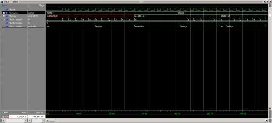
--- Quote Start --- Are you running the test for long enough? it will take 200 clocks for output "key" to be assigned to anything. --- Quote End --- I am running it for 4200 ns. The clock input is 50MHz or 20 ns periods. So 4200 ns should be sufficient. This is the output of ModelSim: http://www.alteraforum.com/forum/attachment.php?attachmentid=13398&stc=1 From your question I gather that the general code looks fine and should work? Thank you.
- Mark as New
- Bookmark
- Subscribe
- Mute
- Subscribe to RSS Feed
- Permalink
- Report Inappropriate Content
Have you check that the counter and state are actually changing?
- Mark as New
- Bookmark
- Subscribe
- Mute
- Subscribe to RSS Feed
- Permalink
- Report Inappropriate Content
--- Quote Start --- Have you check that the counter and state are actually changing? --- Quote End --- Well, I have not checked the counter. I noticed however that when key is set in state init and not in state assign the value shows up in simulation. But when key is assigned in state init AND afterwards in state assign only the last value shows up in simulation..it is like it skipped the init state in that case.
- Mark as New
- Bookmark
- Subscribe
- Mute
- Subscribe to RSS Feed
- Permalink
- Report Inappropriate Content
Is there a way to monitor internal signals with ModelSim? I found this link which suggest it is possible (http://www.alteraforum.com/forum/showthread.php?t=47850&highlight=internal+signal+modelsim). But I could not find a description on how to do it.
Thanks.- Mark as New
- Bookmark
- Subscribe
- Mute
- Subscribe to RSS Feed
- Permalink
- Report Inappropriate Content
If you're doing an RTL simulation, all internals can be put on the waveform. Click on the sim tab, select the module you want to look at then click on the objects tab - all internal signals should be listed.
- Mark as New
- Bookmark
- Subscribe
- Mute
- Subscribe to RSS Feed
- Permalink
- Report Inappropriate Content
Found it. It shows as "Not Logged" in my case. And as "No Data" when added to the wave form.
- Mark as New
- Bookmark
- Subscribe
- Mute
- Subscribe to RSS Feed
- Permalink
- Report Inappropriate Content
Yes, because it wasnt on the wave window when started, modelsim wont log it. Just restart the simulation and run it again. Easiest way is from modelsim console:
restart -f run 1 us- Mark as New
- Bookmark
- Subscribe
- Mute
- Subscribe to RSS Feed
- Permalink
- Report Inappropriate Content
It does look like you should see "key" change. It's not related to your question and just my two cents, but this is not a usual way to structure a FSM. Most people would use a case statement for each state. I'm not sure the tools will even recognize your code as a FSM (should still work though).
It's not clear what you mean by "I already placed a counter in both states so I don't get a timing problem." but the code would be much more clear if you put the counter in a separate process so that it is incremented and reset in one place instead of several.
counter_expired <= '1' when counter = 100 else '0';
counter_proc : process
	begin
		wait until CLK'EVENT and CLK = '1';

		if(counter = 100 or reset_counter = '1') then
			counter <= (others => '0');
		else
			counter <= counter + 1;
		end if;
end process counter_proc;
then in the FSM:
   case state is
   when init =>
       if(counter_expired = '1') then
       ...
       end if;
...
If you are using VHDL 2008, you can access internal signal names in a testbench using the VHDL 2008 external names. Some examples here: http://stackoverflow.com/questions/17287129/vhdl-alias-syntax (http://stackoverflow.com/questions/17287129/vhdl-alias-syntax) In fact, a simulation is sort of useless if you do not do so. Being VHDL, it is ten times more verbose than necessary, but it works. Sorry for the unsought for suggestions; clearly had too much time on my hands today.
- Mark as New
- Bookmark
- Subscribe
- Mute
- Subscribe to RSS Feed
- Permalink
- Report Inappropriate Content
--- Quote Start --- If you are using VHDL 2008, you can access internal signal names in a testbench using the VHDL 2008 external names. Some examples here: http://stackoverflow.com/questions/17287129/vhdl-alias-syntax (http://stackoverflow.com/questions/17287129/vhdl-alias-syntax) In fact, a simulation is sort of useless if you do not do so. Being VHDL, it is ten times more verbose than necessary, but it works. Sorry for the unsought for suggestions; clearly had too much time on my hands today. --- Quote End --- I dont quite know what you're talking about, as simulation always has access to all internal signal names for the waveform. If you have to access internal signals in your testbench to act on them then there is probably something wrong with the design. Btw - modelsim has signalspy to overcome internal access that you get with VHDL 2008, which has been around for a long long time
- Mark as New
- Bookmark
- Subscribe
- Mute
- Subscribe to RSS Feed
- Permalink
- Report Inappropriate Content
One way it works if a synchronous reset is implemented. If that is done the state machine starts in init as it should have done. This was not my doing btw. Credit goes to my TA who found that out.
Below the working code: if rising_edge( clk_50 ) then
if rst = '0' then
state <= init;
else
if state = init AND count = 100 then -- init and assign default char
state <= assign;
key_int( 3 ) <= x"61"; -- ASCII 'a'
key_int( 2 ) <= x"61";
key_int( 1 ) <= x"61";
key_int( 0 ) <= x"61";
count <= ( others => '0' );
-- key <= "11111111111111111111111111111111"; -- debug
elsif state = evaluate then -- check which button is pressed
if button = "10000" then -- button 5: increment ASCII character
state <= assign;
count <= ( others => '0' );
if unsigned( key_int( index ) ) = x"7A" then -- run circular between ASCII char 'a' and 'z'
key_int( index ) <= x"61";
else
key_int( index ) <= key_int( index ) + 1;
end if;
elsif button = "00001" then -- button 1: move to next position (start with 1)
state <= evaluate;
if index = 3 then
index <= 0; -- overflow protection
else
index <= index + 1;
end if;
else
state <= evaluate;
end if;
elsif state = assign AND count = 100 then -- assign any changed keys to output
count <= ( others => '0' );
state <= evaluate;
-- key <= key_int4 & key_int3 & key_int2 & key_int1;
key <= key_int( 3 ) & key_int( 2 ) & key_int( 1 ) & key_int( 0 );
-- key <= "00000000001111111111000000000011"; -- debug
else
count <= count + 1;
end if;
end if; --- Quote Start --- It's not related to your question and just my two cents, but this is not a usual way to structure a FSM. Most people would use a case statement for each state. I'm not sure the tools will even recognize your code as a FSM (should still work though). --- Quote End --- Yes you are right. This is not the standard state machine and if I look at the state machine template from the altera website - link (http://quartushelp.altera.com/15.0/mergedprojects/hdl/vhdl/vhdl_pro_state_machines.htm) or here - link (https://www.altera.com/support/support-resources/design-examples/design-software/vhdl/vhd-state-machine.html) it uses case state ..when=> structure but it does not say it is a nessecity. In the quartus ii handbook volume 1 - link (https://www.google.com/url?sa=t&rct=j&q=&esrc=s&source=web&cd=1&cad=rja&uact=8&sqi=2&ved=0ahukewjelyg5yu_sahujpiykhc1xd40qfggamaa&url=https%3a%2f%2fwww.altera.com%2fen_us%2fpdfs%2fliterature%2fhb%2fqts%2fqts-qps-5v1.pdf&usg=afqjcngnr1gq2_khvwqn9afvdjhqkzw35g&sig2=k1pkspsuefhkqwmvfcrmxq&bvm=bv.150729734,d.ewe) on page 12-50 it only says that to be recognized as a state machine I must use state type like this TYPE Tstate IS (state_0, state_1, state_2, state_3, state_4);
SIGNAL state: Tstate; and also gives a few more suggestions. Maybe that explains the strange behaviour? Maybe the case state ..when=> structure or a reset are necessary? Well, I don't know for sure now but since I got it working with above code I am satisfied for now! Thanks @tricky and @corestar for your help and suggestions!
- Mark as New
- Bookmark
- Subscribe
- Mute
- Subscribe to RSS Feed
- Permalink
- Report Inappropriate Content
--- Quote Start --- I dont quite know what you're talking about, as simulation always has access to all internal signal names for the waveform. If you have to access internal signals in your testbench to act on them then there is probably something wrong with the design. Btw - modelsim has signalspy to overcome internal access that you get with VHDL 2008, which has been around for a long long time --- Quote End --- Tricky, I'm probably not understanding what you are saying. You don't think it is useful for a testbench to access internal signals such as the state, count etc to see what is happening? Waveform windows are nice, but for complicated designs it is helpful to write code to verify results. I tend to agree it would be gross overkill in this case. I rarely actually modify an internal signal, but it can be useful to simulate errors.
- Mark as New
- Bookmark
- Subscribe
- Mute
- Subscribe to RSS Feed
- Permalink
- Report Inappropriate Content
PuqmaStar,
I don't think it explains the strange behavior. It's not a matter of whether or not your way will work so much as efficiency. Your way entails multiple levels of logic. The tools are pretty smart and may be able to optimize it, but I would not depend on that (you could use the Netlist viewers to find out). With a case statement, it can jump to the proper block of hardware. A C/C++ switch statement is similar. The compiler creates a jump table whereas the equivalent if/else code would require evaluating each one until the proper case if found. Also, tools like SignalTap have special ways of handling FSM if it recognizes it. You can tell it to insert the FSM and it will use the named states. If your purpose in the count was to help meet timing, I would just get rid of it. Your simulation will be alot faster. For RTL simulation, timing does not matter and it actually hurts timing in any event. You've added more levels of logic. It looks to me like you properly initialize the state variable and count. Resets are not a bad thing, but it seems like it should have worked before. Not sure why your code caught my interest. Seems like it should work and probably something obvious.- Mark as New
- Bookmark
- Subscribe
- Mute
- Subscribe to RSS Feed
- Permalink
- Report Inappropriate Content
PuqmaStar,
It just bothered me that I could not see what was wrong so I took a few minutes and ran it myself. Seems to work fine for me. I had to addLIBRARY IEEE; at the top of your code to get it to compile and changed count to 5 instead of 100. Perhaps you just missed that in the cut ans paste. Then did a simple test bench: --
-- Simulation tool : ModelSim-Altera (VHDL)
--
LIBRARY ieee;
USE ieee.std_logic_1164.all;
use IEEE.NUMERIC_STD.ALL;
use IEEE.MATH_REAL.ALL;
USE std.textio.all;
USE ieee.std_logic_textio.all;
ENTITY TB IS
END TB;
ARCHITECTURE test_arch OF TB IS
constant clock_period : time := 10 ns;
signal clk : std_logic := '0';
signal clock_running : std_logic := '0';
signal sim_done : std_logic := '0';
signal button : std_logic_vector(5 downto 1) := (others => '0');
signal key : std_logic_vector(31 downto 0) := (others => '0');
component buttonToKey
port (
clk_50 : in std_logic;
button : in std_logic_vector(5 downto 1);
key: out std_logic_vector(31 downto 0)
);
end component;
begin
DUT : buttonToKey
port map (
clk_50 => clk,
button => button,
key => key
);
/*
Clock process
*/
clock_proc : process
begin
if(clock_running = '1') then
wait for clock_period / 2;
clk <= not clk;
elsif(sim_done = '1') then
wait;
else
wait for 20 ns;
end if;
end process;
/*
Test proc
*/
test_proc : process
begin
-- printf("Test proc\n");
-- printf("clock_period = %e\n", clock_period);
clock_running <= '1';
wait for 20 * clock_period;
for i in 1 to 4 loop
button <= "10000";
for j in 1 to 25 loop
wait for 10 * clock_period;
end loop;
button <= "00001";
wait for 2 * clock_period;
end loop;
clock_running <= '0';
sim_done <= '1';
-- printf("done\n");
wait;
end process;
END test_arch;
and DO file to run it: transcript file ""
transcript file transcript.log
transcript on
if {} {
vdel -lib rtl_work -all
}
vlib rtl_work
vmap work rtl_work
vcom -2008 -work work {ButtonToKey.vhd}
vcom -2008 -work work {button_test.vht}
vsim -t 1ps -L altera -L lpm -L sgate -L altera_mf -L altera_lnsim -L fiftyfivenm -L rtl_work -L work -voptargs="+acc" TB
# add wave *
add wave "/TB/CLK"
add wave "/TB/BUTTON"
add wave -hex "/TB/KEY"
add wave -unsigned "/TB/DUT/count"
add wave -decimal "/TB/DUT/index"
add wave "/TB/DUT/state"
# set sim_time
# puts $sim_time
set t0
run -all
set dt - $t0]
puts $dt
wave zoom full
# set PrefMain(Editor) {C:/Windows/System32/notepad.exe}
# edit transcript
and it works just fine: https://www.alteraforum.com/forum/attachment.php?attachmentid=13409 Note the lines in the DO file that add internal signals to the waveform as Tricky suggested. You must be doing something wrong in the way you run the simulation. In any event, now that I know I'm not crazy (regardless of what others think) my interest in the problem is over. Suffice it to say there are all sorts of issues with your code, but since it sounds like a school project you should figure it out yourself. Good luck.
- Subscribe to RSS Feed
- Mark Topic as New
- Mark Topic as Read
- Float this Topic for Current User
- Bookmark
- Subscribe
- Printer Friendly Page