- Mark as New
- Bookmark
- Subscribe
- Mute
- Subscribe to RSS Feed
- Permalink
- Report Inappropriate Content
Hi all!
Recently faced such problem - in the test project there are two PLLs, with input from two base input clocks. One clock is 50 MHz with waveform { 0.000 10.000 } and on also 50 MHz with waveform { 5.000 15.000 }. Project is somemething like that (figure 1).
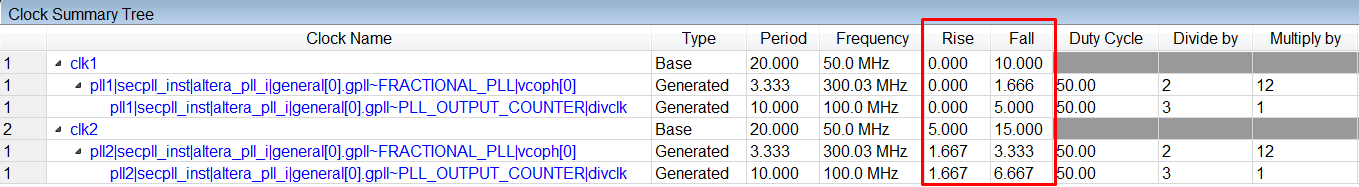
Timequest shows clock tree (figure 2) with a bug - Generated clock (from pll2) starts from 1.667 instead expected 5 ns.
I also attached a project.
Thank you in advance.
--
Best regards,
Ivan
Link Copied
- Mark as New
- Bookmark
- Subscribe
- Mute
- Subscribe to RSS Feed
- Permalink
- Report Inappropriate Content
Can you post just your .sdc instead of your whole project?
- Mark as New
- Bookmark
- Subscribe
- Mute
- Subscribe to RSS Feed
- Permalink
- Report Inappropriate Content
Hi sstrell,
Of course I can!
sdc is simple -
#**************************************************************
# Time Information
#**************************************************************
set_time_format -unit ns -decimal_places 3
#**************************************************************
# Create Clock
#**************************************************************
create_clock -name {clk1} -period 20.000 -waveform { 0.000 10.000 } [get_ports {clk1}]
create_clock -name {clk2} -period 20.000 -waveform { 5.000 15.000 } [get_ports {clk2}]
#**************************************************************
# Create Generated Clock
#**************************************************************
derive_pll_clocks
#**************************************************************
# Set Clock Uncertainty
#**************************************************************
derive_clock_uncertainty
#**************************************************************
--
Best regards,
Ivan
- Mark as New
- Bookmark
- Subscribe
- Mute
- Subscribe to RSS Feed
- Permalink
- Report Inappropriate Content
The clocks you have in the .sdc file are the base clocks, not the generated clocks from the PLL. derive_pll_clocks automatically generates clocks from your PLL settings based on those input reference clocks to the PLL. If you want those clocks coming out of your PLLs (instead of just coming in from the board), you have to set your PLL settings to multiply or divide by 1, basically mirroring the base clocks. Is that what you are trying to do?
- Mark as New
- Bookmark
- Subscribe
- Mute
- Subscribe to RSS Feed
- Permalink
- Report Inappropriate Content
Hi sstrell,
Yes, in sdc there are two base clocks and generated clock automatically generated from PLLs by derive_pll_clocks command.
Let me explain what's going on.
This is created as an example of strange behaviour test project. It has two base clocks, and the whole sdc file is like it should be - one clock is phase shifted from another.
The clocks enter FPGA, go inside two PLLs, and PLLs just multiply clocks by 2 and output them. After that there is a simple code, consisted of two D triggers, one used for catching info from input port and clocked by first_PLL output,
and second trigger catches info from first trigger clocked by second_PLL output. The output of second trigger emerges to output port.
So, after fitter Timequest shows clock tree with a bug - generated clock from second PLL starts from wrong time in ns. It is also interesting that if I change second base clock waveform,
everything is correct for waveforms -waveform { 1.000 11.000 } -waveform { 2.000 12.000 } -waveform {3.000 13.000 } But starting from -waveform { 4.000 14.000 } I'm observing strange behaviour.
--
Best regards,
Ivan
- Mark as New
- Bookmark
- Subscribe
- Mute
- Subscribe to RSS Feed
- Permalink
- Report Inappropriate Content
Hi Ivan,
Can you use the PLL to perform shifting?
Thanks.
(1507114046)
- Mark as New
- Bookmark
- Subscribe
- Mute
- Subscribe to RSS Feed
- Permalink
- Report Inappropriate Content
Hi KYeoh,
Yes I can, but I don't want to perform clock shifting using PLL. This example is not a real project but a test project, so I don't need to change it.
--
Best regards,
Ivan
- Mark as New
- Bookmark
- Subscribe
- Mute
- Subscribe to RSS Feed
- Permalink
- Report Inappropriate Content
Hi IDeyn,
The clock you're looking at, divclk, is not directly derived from refclk. Vcoph[0] first derived from refclk. The rise and fall times for vcoph[0] have to be between 1.667 and the period of 3.333, which is why we see the drop in rise time at any refclk offset greater than 3.333. divclk inherits its rise and fall times from vcoph[0], not refclk.
If you want to force divclk to mirror the offset you add to refclk, you can overwrite its waveform with the -offset option as follows:
create_generated_clock -name {ip1_inst|altera_pll_i|general[0].gpll~PLL_OUTPUT_COUNTER|divclk} -source {ip1_inst|altera_pll_i|general[0].gpll~PLL_OUTPUT_COUNTER|vco0ph[0]} -divide_by XX -multiply_by YY -duty_cycle 50.00 -offset X.XXX { ip1_inst|altera_pll_i|general[0].gpll~PLL_OUTPUT_COUNTER|divclk }
Thanks
- Mark as New
- Bookmark
- Subscribe
- Mute
- Subscribe to RSS Feed
- Permalink
- Report Inappropriate Content
Hi YY,
Thank you for your answer. Ok, I will try create_generated_clock with -offset option.
I understand that I see the derivative from vco clock. But for me it looks that derive_pll_clocks in that case (as you said "mirroring the offset")
is error-prone, so maybe it is useful to upgrade this command or explicitly mention that in manual.
Best regards,
Ivan
- Mark as New
- Bookmark
- Subscribe
- Mute
- Subscribe to RSS Feed
- Permalink
- Report Inappropriate Content
Hi YY,
I've just tried create_generated_clock command.
I wrote commands WITHOUT -offset option and achieved proper results using Report Clocks command.
Here are exact commands:
create_generated_clock -name {pll1|secpll_inst|altera_pll_i|general[0].gpll~PLL_OUTPUT_COUNTER|divclk} -source {pll1|secpll_inst|altera_pll_i|general[0].gpll~FRACTIONAL_PLL|vcoph[0]} -divide_by 1 -multiply_by 2 -duty_cycle 50.00 -offset 0.000 {pll1|secpll_inst|altera_pll_i|general[0].gpll~PLL_OUTPUT_COUNTER|divclk}
create_generated_clock -name {pll2|secpll_inst|altera_pll_i|general[0].gpll~PLL_OUTPUT_COUNTER|divclk} -source {pll2|secpll_inst|altera_pll_i|general[0].gpll~FRACTIONAL_PLL|vcoph[0]} -divide_by 1 -multiply_by 2 -duty_cycle 50.00 -offset 0.000 {pll2|secpll_inst|altera_pll_i|general[0].gpll~PLL_OUTPUT_COUNTER|divclk}
I attached figure showing that results are right, as expected.
So, the conclusion for me right now is that create_generated_clocks works better than derive_pll_clocks. And it is a potential mislead.
Best regards,
Ivan
- Mark as New
- Bookmark
- Subscribe
- Mute
- Subscribe to RSS Feed
- Permalink
- Report Inappropriate Content
I guess, when you're shifting the clocks manually without using the PLLs phase shift feature, then you would have to generate the output clocks manually using the create_generated_clocks constraints. The derive_pll_clocks works well when the PLL is used for phase shifting the clocks. It generates the required clocks with respect to the PLL configuration settings.
- Mark as New
- Bookmark
- Subscribe
- Mute
- Subscribe to RSS Feed
- Permalink
- Report Inappropriate Content
Hi Abe ,
Thank you very much for your answer.
It can be a real design case, where clocks are shifted on board, so we need a way to describe it in TQ.
So, again it looks that derive_pll_clocks can't be used with input clocks with phase shift, in that case we need to manually write generated_clocks, which is inconvenient.
In my opinion, it is a bug and it will be good if it will be corrected.
--
Best regards,
Ivan
- Subscribe to RSS Feed
- Mark Topic as New
- Mark Topic as Read
- Float this Topic for Current User
- Bookmark
- Subscribe
- Printer Friendly Page