- Mark as New
- Bookmark
- Subscribe
- Mute
- Subscribe to RSS Feed
- Permalink
- Report Inappropriate Content
Hello,
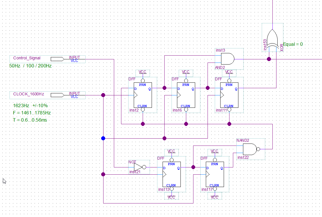
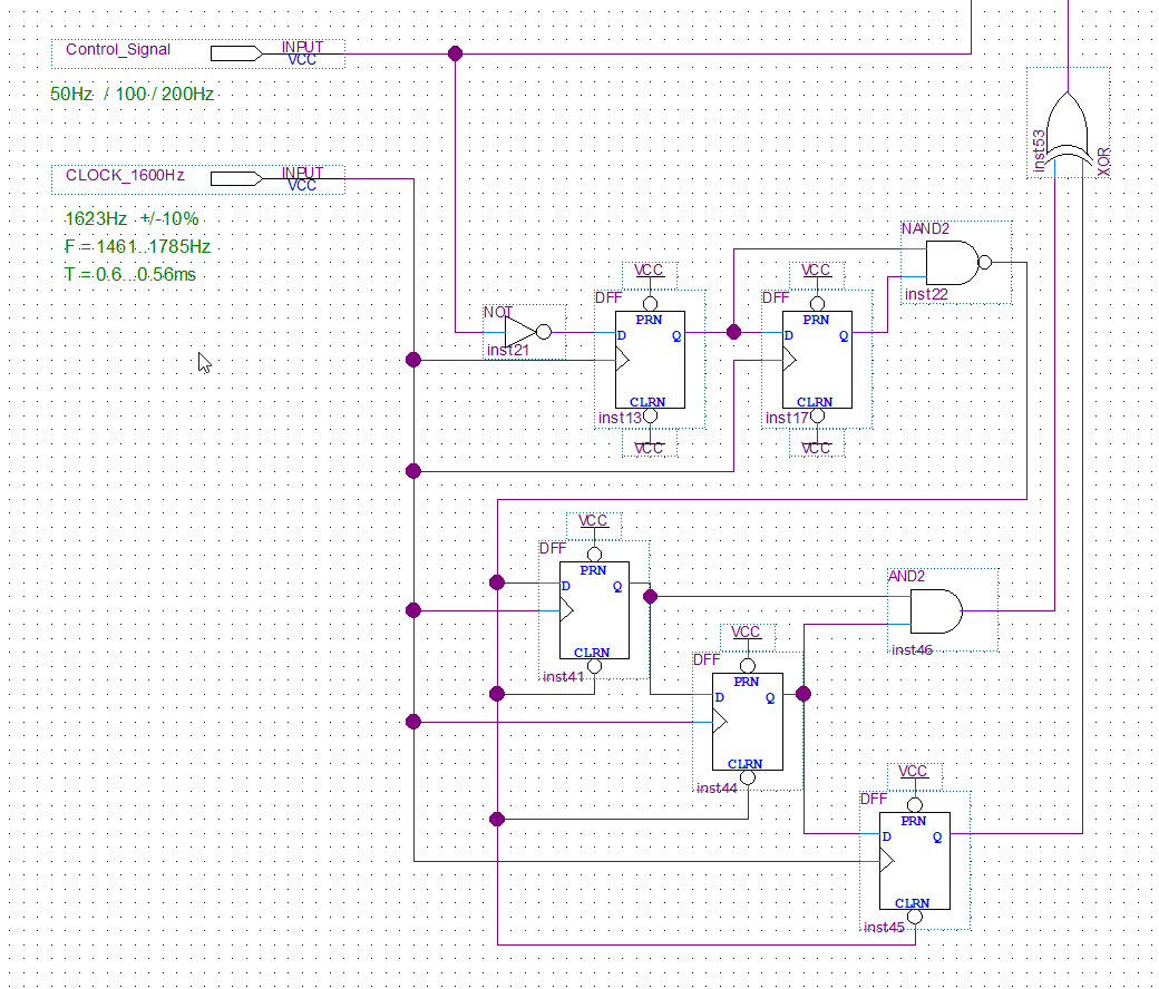
I am running a simulation in ModelSim using the .vho file generated during compilation of my project containing a .bdf file in Quartus Prime. I was getting inconsistent behaviour in a DFF chain. Upon closer inspection I noticed that the clocks at three DFFs were not entirely in synch, one was always several delta cycles off. Redrawing the .bdf file with exactly the same components fixed the problem, but I am at a complete loss as to what could have caused the clocks to be out of synch. Has anyone experienced this issue and knows what caused it? I've attached screenshots of the part of the .bdf design in question (one with the clocks in synch, and one with the clocks slightly out of synch) along with the corresponding simulation results.
As to the software used:
Quartus Prime Version 18.1.0 Build 625 09/12/2018 SJ Lite Edition
ModelSim - INTEL FPGA STARTER EDITION 10.5b (Revision 2016.10) (Quartus Prime 18.1)
Thanks for your help!
Felix
Link Copied
- Mark as New
- Bookmark
- Subscribe
- Mute
- Subscribe to RSS Feed
- Permalink
- Report Inappropriate Content
- Mark as New
- Bookmark
- Subscribe
- Mute
- Subscribe to RSS Feed
- Permalink
- Report Inappropriate Content
Hi,
How i fixed it: I deleted that part of the .bdf and redrew it using exactly the same DFF type. Why this worked i don't understand, which is what I'm trying to figure out.
I just compared the .vho files, specifically the port mapping of the clock inputs of the DFFs in question and noticed the following:
inst2: clk => \CLOCK_1600Hz~inputclkctrl_outclk\
inst41: clk => \CLOCK_1600Hz~inputclkctrl_outclk\
inst6: clk => \CLOCK_1600Hz~input_o\
inst44: clk => \CLOCK_1600Hz~inputclkctrl_outclk\
inst11: clk => \CLOCK_1600Hz~inputclkctrl_outclk\
inst45: clk => \CLOCK_1600Hz~inputclkctrl_outclk\
I paired the "equivalent" DFFs to show that the DFF that had a clock signal that had some delta was actually mapped to a different signal than the others. I'll include the parts in the .vho that show where these two signals come from. I don't understand why this happens though.
-- Location: IOIBUF_X0_Y4_N15
\CLOCK_1600Hz~input\ : fiftyfivenm_io_ibuf
-- pragma translate_off
GENERIC MAP (
bus_hold => "false",
listen_to_nsleep_signal => "false",
simulate_z_as => "z")
-- pragma translate_on
PORT MAP (
i => ww_CLOCK_1600Hz,
o => \CLOCK_1600Hz~input_o\);
\CLOCK_1600Hz~inputclkctrl\ : fiftyfivenm_clkctrl
-- pragma translate_off
GENERIC MAP (
clock_type => "global clock",
ena_register_mode => "none")
-- pragma translate_on
PORT MAP (
inclk => \CLOCK_1600Hz~inputclkctrl_INCLK_bus\,
devclrn => ww_devclrn,
devpor => ww_devpor,
outclk => \CLOCK_1600Hz~inputclkctrl_outclk\);
Thanks!
Regards,
Felix
- Subscribe to RSS Feed
- Mark Topic as New
- Mark Topic as Read
- Float this Topic for Current User
- Bookmark
- Subscribe
- Printer Friendly Page