- Mark as New
- Bookmark
- Subscribe
- Mute
- Subscribe to RSS Feed
- Permalink
- Report Inappropriate Content
hello everybody
im quite new in developing for FPGA. I have started wih DE0-nano board. im learning just programming an easy FSM that performs elementary operations. i have followed the tutorial for simulating the circuit with Modelsim-Altera. no problem with the flow of functional simulation. the operations are simulated in the sequence as expected. While trying to create timing simulation with the same Modelsim (gate level simulation) my FSM does not work as expected. The state of FSM is update in not controlled way. I have made several tries and i have the suspect to have wrong code the two process statement that concurrency run. The source code is in VHDL. So same code in VHD work in functional simulation and worngly work in gate level simulation. i would like to fix this issue to learn more about FPGA. Thank youLink Copied
- Mark as New
- Bookmark
- Subscribe
- Mute
- Subscribe to RSS Feed
- Permalink
- Report Inappropriate Content
without the code, we cant really tell what the problem is. Is the design fully syncrhonous?
- Mark as New
- Bookmark
- Subscribe
- Mute
- Subscribe to RSS Feed
- Permalink
- Report Inappropriate Content
--- Quote Start --- without the code, we cant really tell what the problem is. Is the design fully syncrhonous? --- Quote End --- can i post the code here? the project is simple FSM with asyncrohous input and one clock to trigger all the transiction inside
- Mark as New
- Bookmark
- Subscribe
- Mute
- Subscribe to RSS Feed
- Permalink
- Report Inappropriate Content
sorry for the alert,
but it's safe to post code here?- Mark as New
- Bookmark
- Subscribe
- Mute
- Subscribe to RSS Feed
- Permalink
- Report Inappropriate Content
--- Quote Start --- sorry for the alert, but it's safe to post code here? --- Quote End --- Yes. Post the code so we can try and work out whats wrong.
- Mark as New
- Bookmark
- Subscribe
- Mute
- Subscribe to RSS Feed
- Permalink
- Report Inappropriate Content
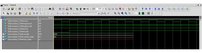
following the code that works in RTL simulation but not in gate level simulation.
IN particular, in gate level sim, the counter is not increasing and the state jumps directly into '11' that is not correct. Thanks for the help
LIBRARY ieee;
USE ieee.std_logic_1164.all;
USE ieee.std_logic_unsigned.all;
USE ieee.numeric_std.all;
ENTITY somma_FSM IS
GENERIC
	(
		WAIT_STATE :STD_LOGIC_VECTOR(1 DOWNTO 0) := B"00";
		WORK_STATE :STD_LOGIC_VECTOR(1 DOWNTO 0) := B"01";
		END_STATE :STD_LOGIC_VECTOR(1 DOWNTO 0) := B"11"
	);
	PORT
	(
		ingressoA : IN STD_LOGIC;
		ingressoB : IN STD_LOGIC;
		inizia : IN STD_LOGIC;
		resetn :IN STD_LOGIC;
		clock : IN STD_LOGIC;
		finito : OUT STD_LOGIC;
		somma : OUT STD_LOGIC;
		resto : OUT STD_LOGIC
	);
END somma_FSM;
ARCHITECTURE somma_FSM_architecture OF somma_FSM IS
SIGNAL current_state :STD_LOGIC_VECTOR(1 DOWNTO 0) := B"00";
SIGNAL next_state :STD_LOGIC_VECTOR(1 DOWNTO 0) := B"00";
SIGNAL counter :STD_LOGIC_VECTOR(2 DOWNTO 0) := B"000";
SIGNAL resto_in :STD_LOGIC := '0';
SIGNAL resto_out :STD_LOGIC := '0';
BEGIN
PROCESS(inizia, current_state, counter)
	BEGIN
		CASE(current_state) IS
			WHEN B"00" =>
				IF (inizia = '1') THEN
					next_state <= B"01";
				ELSE
					next_state <= B"00";
				END IF;
			WHEN B"01" =>
					IF (counter = B"111") THEN
						next_state <= B"11";
--						finito <= '1';
					END IF;
			WHEN B"11"	=>
 					next_state <= B"00";
			WHEN OTHERS =>
		END CASE;
	END PROCESS;
PROCESS(clock)
BEGIN
		IF (resetn = '0') THEN
			current_state <= WAIT_STATE;
			counter <= (OTHERS => '0');
		ELSE IF ((clock'EVENT) AND (clock = '0')) THEN
			current_state <= next_state;
			IF (current_state = B"00") THEN
				counter <= (OTHERS => '0');
			ELSE IF (current_state = B"01") THEN
				counter <= counter + '1';
				resto_in <= resto_out;
				END IF;
			END IF;
		END IF;
	END IF;
END PROCESS;
 somma <= ingressoA XOR ingressoB XOR resto_in;
 resto_out  <= (ingressoA AND ingressoB) OR (ingressoA AND resto_in) OR (ingressoB AND resto_in);
 resto <= resto_out;
 finito <= '1' WHEN current_state =B"11";

END somma_FSM_architecture;
- Mark as New
- Bookmark
- Subscribe
- Mute
- Subscribe to RSS Feed
- Permalink
- Report Inappropriate Content
I do notice that reset is not in the sensitivity list of the 2nd process.
But can you post your testbench? Did you provide any timing specifications to the design?- Mark as New
- Bookmark
- Subscribe
- Mute
- Subscribe to RSS Feed
- Permalink
- Report Inappropriate Content
--- Quote Start --- I do notice that reset is not in the sensitivity list of the 2nd process. But can you post your testbench? Did you provide any timing specifications to the design? --- Quote End --- reset signal is not used. test bench is the following: http://www.alteraforum.com/forum/attachment.php?attachmentid=13078&stc=1
- Mark as New
- Bookmark
- Subscribe
- Mute
- Subscribe to RSS Feed
- Permalink
- Report Inappropriate Content
reset is no used.
any time specification provided test bench is the following: https://www.alteraforum.com/forum/attachment.php?attachmentid=13079
- Mark as New
- Bookmark
- Subscribe
- Mute
- Subscribe to RSS Feed
- Permalink
- Report Inappropriate Content
That is not a testbench - that ios the waveform output from the design.
What code are you using to test your design?- Mark as New
- Bookmark
- Subscribe
- Mute
- Subscribe to RSS Feed
- Permalink
- Report Inappropriate Content
--- Quote Start --- That is not a testbench - that ios the waveform output from the design. What code are you using to test your design? --- Quote End --- synthesis code is VHDL ModelSim code is converted in Verilog
- Mark as New
- Bookmark
- Subscribe
- Mute
- Subscribe to RSS Feed
- Permalink
- Report Inappropriate Content
I Notice the next_state and finito signal is not assigned in all branches, so it will create latches. This might be what is causing the problems.
- Mark as New
- Bookmark
- Subscribe
- Mute
- Subscribe to RSS Feed
- Permalink
- Report Inappropriate Content
--- Quote Start --- I Notice the next_state and finito signal is not assigned in all branches, so it will create latches. This might be what is causing the problems. --- Quote End --- what do you mean for .. is not assigned in all branches?
- Mark as New
- Bookmark
- Subscribe
- Mute
- Subscribe to RSS Feed
- Permalink
- Report Inappropriate Content
In an asynchronous process, all signals must be assigned in all cases, otherwise latchea will be created.
For example, when current state is 01, next state is only assigned when the counter gets to 7, otherwise it holds its state. This creates a latch. You must at least assign it to current state to avoid the latch. The same for finito. It is only assigned here. This creates a latch.- Mark as New
- Bookmark
- Subscribe
- Mute
- Subscribe to RSS Feed
- Permalink
- Report Inappropriate Content
im going literally crazy ..
i have modified the code in this way
LIBRARY ieee;
USE ieee.std_logic_1164.all;
USE ieee.std_logic_unsigned.all;
USE ieee.numeric_std.all;
ENTITY somma_FSM IS
GENERIC
	(
		WAIT_STATE :STD_LOGIC_VECTOR(1 DOWNTO 0) := B"00";
		WORK_STATE :STD_LOGIC_VECTOR(1 DOWNTO 0) := B"01";
		END_STATE :STD_LOGIC_VECTOR(1 DOWNTO 0) := B"11"
	);
	PORT
	(
		ingressoA : IN STD_LOGIC;
		ingressoB : IN STD_LOGIC;
		inizia : IN STD_LOGIC;
		resetn :IN STD_LOGIC;
		clock : IN STD_LOGIC;
		finito : OUT STD_LOGIC;
		somma : OUT STD_LOGIC;
		resto : OUT STD_LOGIC
	);
END somma_FSM;
ARCHITECTURE somma_FSM_architecture OF somma_FSM IS
SIGNAL current_state :STD_LOGIC_VECTOR(1 DOWNTO 0);
SIGNAL next_state :STD_LOGIC_VECTOR(1 DOWNTO 0);
SIGNAL counter :STD_LOGIC_VECTOR(2 DOWNTO 0);
SIGNAL resto_in :STD_LOGIC := '0';
SIGNAL resto_out :STD_LOGIC := '0';
BEGIN
PROCESS(inizia, current_state, counter)
	BEGIN
		CASE(current_state) IS
			WHEN B"00" =>
				IF (inizia = '1') THEN
					next_state <= B"01";
					finito <= '0';
					ELSE
					next_state <= B"00";
					finito <= '0';
				END IF;
			WHEN B"01" =>
					IF (counter = B"111") THEN
						next_state <= B"11";
						finito <= '1';
					ELSE
						next_state <= B"01";
						finito <= '0';
					END IF;
			WHEN B"11"	=>
 					next_state <= B"00";
					finito <= '0';
			WHEN OTHERS =>
		END CASE;
	END PROCESS;
PROCESS(resetn,clock)
BEGIN
		IF (resetn = '0') THEN
			current_state <= WAIT_STATE;
			counter <= (OTHERS => '0');
			ELSE IF ((clock'EVENT) AND (clock = '0')) THEN
				current_state <= next_state;
				IF (current_state = B"00") THEN
					counter <= (OTHERS => '0');
					ELSE IF (current_state = B"01") THEN
						counter <= counter + '1';
						resto_in <= resto_out;
					END IF;
				END IF;
			END IF;
		END IF;
END PROCESS;
 somma <= ingressoA XOR ingressoB XOR resto_in;
 resto_out  <= (ingressoA AND ingressoB) OR (ingressoA AND resto_in) OR (ingressoB AND resto_in);
 resto <= resto_out;
 --finito <= '1' WHEN current_state =B"11";

END somma_FSM_architecture;
i got these waveforms ... https://www.alteraforum.com/forum/attachment.php?attachmentid=13083
- Mark as New
- Bookmark
- Subscribe
- Mute
- Subscribe to RSS Feed
- Permalink
- Report Inappropriate Content
Please post your test bench code, without it we cannot test your code.
- Mark as New
- Bookmark
- Subscribe
- Mute
- Subscribe to RSS Feed
- Permalink
- Report Inappropriate Content
--- Quote Start --- That is not a testbench - that ios the waveform output from the design. What code are you using to test your design? --- Quote End --- Sorry for the ignorance, For test bench code you mean eda netlist file in verilog generated for modelsim?
- Mark as New
- Bookmark
- Subscribe
- Mute
- Subscribe to RSS Feed
- Permalink
- Report Inappropriate Content
--- Quote Start --- Sorry for the ignorance, For test bench code you mean eda netlist file in verilog generated for modelsim? --- Quote End --- No - the testbench is the code you use to test your code - you have to generate inputs for the design somehow...
- Mark as New
- Bookmark
- Subscribe
- Mute
- Subscribe to RSS Feed
- Permalink
- Report Inappropriate Content
--- Quote Start --- No - the testbench is the code you use to test your code - you have to generate inputs for the design somehow... --- Quote End --- Sorry, i do not use test bench. I perform compilation in quartus, open modelsim, run the simulation and using modelsim Waveforms editors to provide input to dut. In wave window i add output waveforms to see what happens
- Mark as New
- Bookmark
- Subscribe
- Mute
- Subscribe to RSS Feed
- Permalink
- Report Inappropriate Content
What code are you using to test your design?
- Mark as New
- Bookmark
- Subscribe
- Mute
- Subscribe to RSS Feed
- Permalink
- Report Inappropriate Content
--- Quote Start --- i got these waveforms ... https://www.alteraforum.com/forum/attachment.php?attachmentid=13083 --- Quote End --- This picture is too small and low quality we cannot see the actual waveforms. And without the test it is impossible to tell whats going on. But the appearance of U or X usually means that something is driving them that way. You should be able to add any signal to the wave window to trace back the drivers to see what is causing the problem. There isnt anything obviously wrong in your code., other than not assigning next_state and finito in the "others" case to cover their state when current state is "10" or "UU" or "XX". It could be something to do with this. Otherwise I can only assume a test bench issue.
- Subscribe to RSS Feed
- Mark Topic as New
- Mark Topic as Read
- Float this Topic for Current User
- Bookmark
- Subscribe
- Printer Friendly Page