- Mark as New
- Bookmark
- Subscribe
- Mute
- Subscribe to RSS Feed
- Permalink
- Report Inappropriate Content
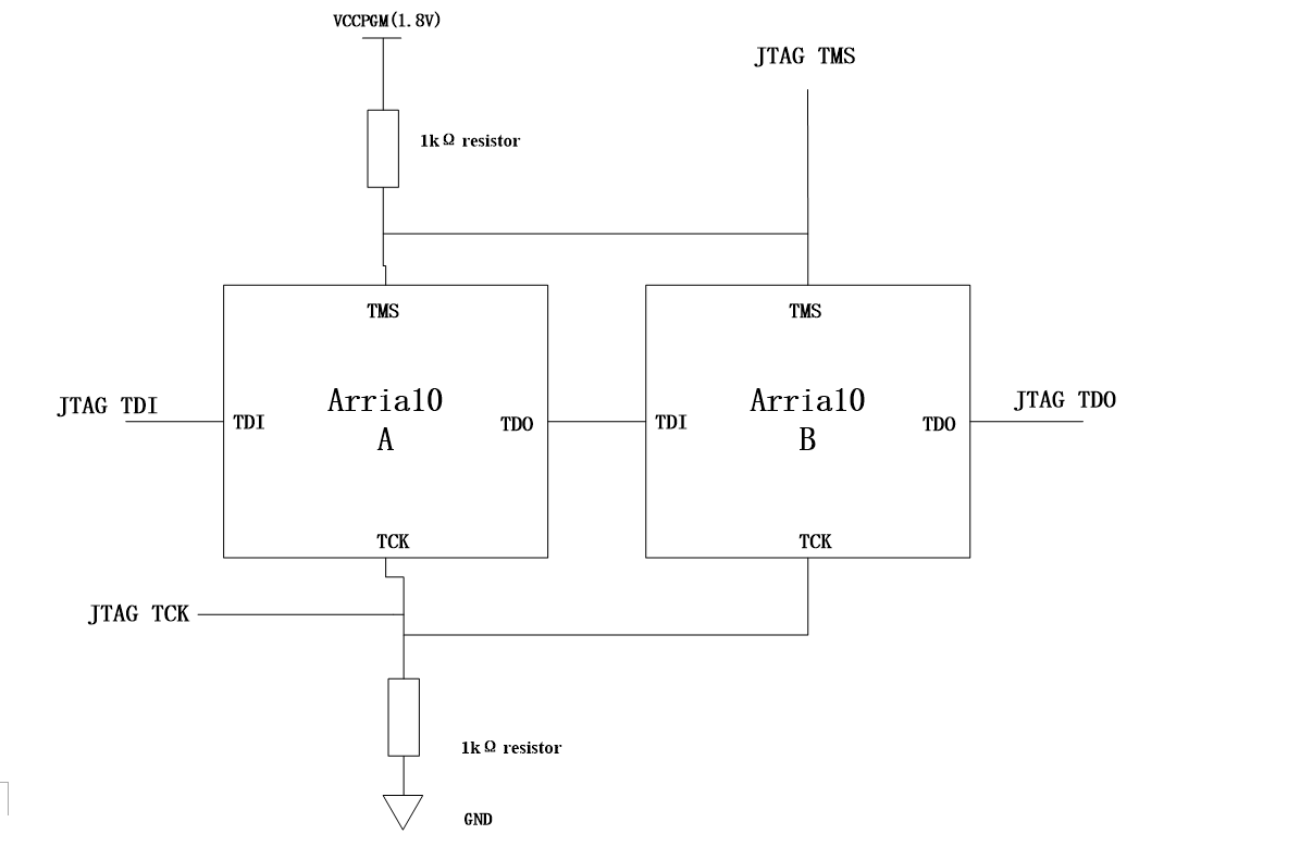
There’re two Arria 10 SoCs in my design,
the follwoing picture indicates the JTAG chain on board. Chip A and Chip B
share the same TCK & TMS. TCK is pulled down to GND and TMS is pulled up to
VCCPGM(1.8V), according to the pin guidelines. TDO of Chip A connects to TDI of
Chip B. TDI of Chip A is pulled up to VCCPGM(1.8V).
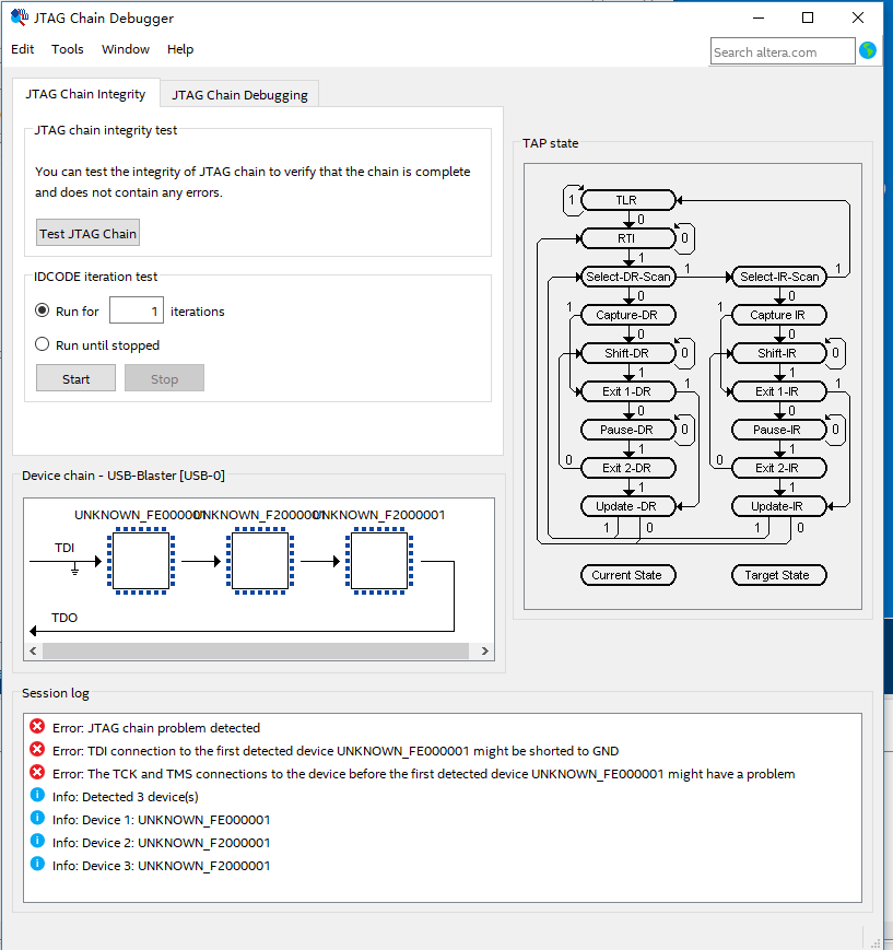
After power up, programmer in quartus
cannot scan the JTAG chain, and reminds me the following errors when I run
“Test JTAG chain”:
!Error: JTAG chain problem detected
!Error: TDI connection to the first
detected device UNKNOWN_FE000001 might be shorted to GND
!Error: The TCK and TMS connections to the
device before the first detected device UNKNOWN_FE000001 might have a problem
!Info: Detected 3 device(s)
!Info: Device 1: UNKNOWN_FE000001
!Info: Device 2: UNKNOWN_F2000001
!Info: Device 3: UNKNOWN_F2000001
Also, the following error pops out when I
try “JTAG Chain Debugging”:
!Error: Incorrect clock value
The impedance between JTAG TDI and GND is
1.029KΩ.
The impedance between the output of
VCCPGM(1.8V) regulator and GND is 24Ω.
Is the Arria 10 SoC JTAG port permanently
damaged?
What can I do to access the JTAG chain?
Thanks, regards.
Link Copied
- Mark as New
- Bookmark
- Subscribe
- Mute
- Subscribe to RSS Feed
- Permalink
- Report Inappropriate Content
Make sure nCONFIG isn't pulled low - as I think that prevents a valid JTAG ID from being returned (at least, that's what I've experienced in the past).
- Mark as New
- Bookmark
- Subscribe
- Mute
- Subscribe to RSS Feed
- Permalink
- Report Inappropriate Content
Thank you very much for your answer. That might explain the UNKNOW_DEVICE problem, but I'm still wondering why programmer report TDI might be shorted to GND.
- Mark as New
- Bookmark
- Subscribe
- Mute
- Subscribe to RSS Feed
- Permalink
- Report Inappropriate Content
- Mark as New
- Bookmark
- Subscribe
- Mute
- Subscribe to RSS Feed
- Permalink
- Report Inappropriate Content
Thank you very much for your answer, John.
How can I confirm the device in reset state or not?
Besides, should I connect the TDI of usb blaster to the device's TDI or TDO?
Thanks, regards.
- Mark as New
- Bookmark
- Subscribe
- Mute
- Subscribe to RSS Feed
- Permalink
- Report Inappropriate Content
- Mark as New
- Bookmark
- Subscribe
- Mute
- Subscribe to RSS Feed
- Permalink
- Report Inappropriate Content
Thank you. Here's my update.
The waveforms of both devices' nSTATUS pins are rectangular waves, and one's frequency is 516Hz while the other one is 542Hz.
I refer to relevant hanbook, after sampling MSEL, nSTATUS is released high and then pulled low if configuration error occurs.
In my design, I define MSEL=011 with pull-up resistor to VCCPGM and pull-down reststor to GND, which indicates AS×4 mode. Each of the devices has an attached EPCQL1024.
Is it possible that the devices try to load configuration data from EPCQL1024 after power-up then fail, so the waveform of nSTATUS is rectangular wave, resulting the reset of the device and JTAG periodically?
If the answer is yes, how can I solve this problem to relase the device from reset state?
Thanks, regards.
- Mark as New
- Bookmark
- Subscribe
- Mute
- Subscribe to RSS Feed
- Permalink
- Report Inappropriate Content
- Mark as New
- Bookmark
- Subscribe
- Mute
- Subscribe to RSS Feed
- Permalink
- Report Inappropriate Content
Thank you for your answer.
I changed the define of MSEL from 011(AS mode) to 000(JTAG mode), now nSTATUS pin is high, as well as nCONFIG.
But the programmer still reminds me "unable to scan device chain" as you can see in the following picture.
The oscilloscope can detect pulses on TDO pin when I click "auto detect".
Currently I prefer to access the device via JTAG rather than AS interface, so I hope to find a solution to access the JTAG chain.
Any suggestions?
Thanks, regards.

- Mark as New
- Bookmark
- Subscribe
- Mute
- Subscribe to RSS Feed
- Permalink
- Report Inappropriate Content
Hi, here's some facts that I can confirm:
1. The voltage values of VCCPGM, VCCIO_HPS, VCCIOREF_HPS, A10VCCPLL_HPS and A10VCCA_PLL are correct, range from 1.824V to 1.829V.
2. I design the JTAG circuit following the instructions in the handbook named "Configuration, Design Security, and Remote System Upgrades in Arria 10 Devices", as you can see in the following picture. All the resistors are soldered well.

3. The impedance values between JTAG pins(TDI, TDO, TCK and TMS) and GND range from 1.028KΩ to 1.180MΩ, and the impedance values between JTAG pins and VCCPGM range from 1KΩ to 1.180MΩ.
4. After power-up, TDI and TMS are high, TCK is low and the voltage of TDO is 0.612V. MSEL=000 and both nCONFIG and nSTATUS are high.
5. When I run "Auto detect" in Programmer, a error message occurs: "unable to scan device chain. Can't scan JTAG chain. Do you want to open the JTAG Chain Debugger to troubleshoot the JTAG chain?", as you can see in the following picture.

6. When I run "Test JTAG Chain", the Programmer reminds that TDI might be shorted to GND,and unknown devices detected, as you can see in the following picture.

7. When I run "Auto detect" in Programmer, the oscilloscope can capture waveforms of TDI, TCK, TDO and TMS, as you can see in the following pictures.


.jpg")

And here's my questions:
1. Is the JTAG port of Arria 10 permanently damaged? How can I confirm that?
2. Currently I'm using Altera Usb Blaster, does usb blaster support Arria 10 SoC? Should I change to Altera Usb blaster II?
3. Do you have more suggestions for me to access the JTAG chain?
Thanks, regards.
- Mark as New
- Bookmark
- Subscribe
- Mute
- Subscribe to RSS Feed
- Permalink
- Report Inappropriate Content
- Mark as New
- Bookmark
- Subscribe
- Mute
- Subscribe to RSS Feed
- Permalink
- Report Inappropriate Content
I can confirm there're 2 devices in the JTAG chain. The part type is 10AS066N3F40.
Ideally I should see 4 components in JTAG Chain Debugger, 2 FPGAs and 2 HPSs.
So far I have two auto-detect results, with 3 components and 5 components respectively, as you can see in the following pictures. Both of the results have UNKNOWN_FE000001 as the first component.
I'm also wondering why there're one more device that I can't explain.
Thanks, regrads. 

- Mark as New
- Bookmark
- Subscribe
- Mute
- Subscribe to RSS Feed
- Permalink
- Report Inappropriate Content
- Mark as New
- Bookmark
- Subscribe
- Mute
- Subscribe to RSS Feed
- Permalink
- Report Inappropriate Content
- Subscribe to RSS Feed
- Mark Topic as New
- Mark Topic as Read
- Float this Topic for Current User
- Bookmark
- Subscribe
- Printer Friendly Page