- Mark as New
- Bookmark
- Subscribe
- Mute
- Subscribe to RSS Feed
- Permalink
- Report Inappropriate Content
Hello Dear Community,
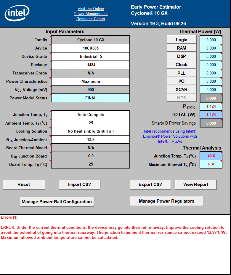
We want to start new design using Cyclone 10GX (obviously it will be the fast available Inte FPGA). I start by setting up the EPE file to size the power supplies. I am surprised how much static power of the Cyclone 10 GX is big (1.124W). This power is three time bigger at 60°C.
Can you confirm that it is a correct computing, and no bug is known of the epe-excel file? I couldn't get any information on the related datasheet of the device.
Also, from the epe-file, it seems that the device can not be used in this configuration (no heatsink with still air) because of the θja: Why in no heatsink still air configuration the board thermal model is not included in the calculation? Does it mean that it could make it using the Cyclone 10 GX with no heatsink and still air at 65°C?
Thank you
Link Copied
- Mark as New
- Bookmark
- Subscribe
- Mute
- Subscribe to RSS Feed
- Permalink
- Report Inappropriate Content
Hi,
The values that you are seeing are for Maximum Power characteristics. For board, the designers should consider these values. There is no problem in EPE sheet.
I will take the query to internal team on why board thermal model is not considered for no heat sink configuration.
Regards
- Mark as New
- Bookmark
- Subscribe
- Mute
- Subscribe to RSS Feed
- Permalink
- Report Inappropriate Content
Hi,
I found this information on the EPE user guide for Cyclone 10 GX, https://www.intel.com/content/www/us/en/programmable/documentation/jlc1485535013520.html#jya1492549887577
+++++++++++++++++++++++++++++++++++++++
Not Using a Heatsink
When you do not use a heat sink, the major paths of power dissipation are from the device to the air. You can refer to this as a junction-to-ambient thermal resistance. In this case, there are two significant junction-to-ambient thermal resistance paths:
- From the device through the case to the air
- From the device to the board
Figure 8. Thermal Representation without a Heat Sink
In the model used in the EPE spreadsheet, power is dissipated through the case and board. The θJA values are calculated for differing air flow options accounting for the paths through the case and through the board.
+++++++++++++++++++++++++++++++++++++++++++
It indicates that even though there is no heat sink, the tool considers a board thermal model typical value in calculation of θJA. So, it is not ignoring it.
For the with heat sink configurations, it allows user to add this value. "The path through the board has less impact than the path to air."
Regards
- Subscribe to RSS Feed
- Mark Topic as New
- Mark Topic as Read
- Float this Topic for Current User
- Bookmark
- Subscribe
- Printer Friendly Page