- Mark as New
- Bookmark
- Subscribe
- Mute
- Subscribe to RSS Feed
- Permalink
- Report Inappropriate Content
Hi,
I have got a problem with the Dual Configuration IP on a Max 10M08DAF256I7G.
I'm using Quartus Version 17.1.
- I write the config_sel_overwrite and config_sel at Offset 1
- Read the busy signal at Offset 1, if it goes low I proceed
- Write 1 at Offset 0 to trigger reconfiguration
On 3 out of 250 devices the reconfiguration it not triggered. When I'm triggering the read of the input register and reading back the config_sel_overwrite and config_sel at offset 7. This bits are written correctly, but writing a 1 at Offset 0 seems to have no effect.
The IP Core and my state machine are both running on the same 40 MHz clock.
Best regards
Tom
Link Copied
- Mark as New
- Bookmark
- Subscribe
- Mute
- Subscribe to RSS Feed
- Permalink
- Report Inappropriate Content
I mean read busy signal at offset 3, of course.
- Mark as New
- Bookmark
- Subscribe
- Mute
- Subscribe to RSS Feed
- Permalink
- Report Inappropriate Content
Hi,
After you performed reconfiguration, do you try to read the offset 3 to see it it is busy?
- Mark as New
- Bookmark
- Subscribe
- Mute
- Subscribe to RSS Feed
- Permalink
- Report Inappropriate Content
Hello John,
yes I do. The sequence in the state machine is
- addr="000", writedata = "01"
- addr="000", writedata = "01", write='1' (triggering the reconfiguration)
- addr="011", read='1'
- addr="011", read='1' and wait till readdata(0) is '0'
- Mark as New
- Bookmark
- Subscribe
- Mute
- Subscribe to RSS Feed
- Permalink
- Report Inappropriate Content
Hi,
Does it mean that the dual configuration IP is stuck in busy state after you performed reconfiguration?
- Mark as New
- Bookmark
- Subscribe
- Mute
- Subscribe to RSS Feed
- Permalink
- Report Inappropriate Content
Hi John,
it is not stuck there. It actually never gets busy at all, after writing.
- Mark as New
- Bookmark
- Subscribe
- Mute
- Subscribe to RSS Feed
- Permalink
- Report Inappropriate Content
Hi,
Just would like to confirm if all the board is program with the same pof file?
Are you able to configure to Image1 during power on using external CONFIG_SEL pin?
- Mark as New
- Bookmark
- Subscribe
- Mute
- Subscribe to RSS Feed
- Permalink
- Report Inappropriate Content
Hi,
yes it is the same pof file and I can change to Image 1 with the config_sel pin at startup.
I also tested it with writing the config_sel=1 and config_sel_overwrite=0 to just triggering the rconfig.
On the good boards I read the input_reg with 0 because of the reconfiguration and on the three that do not reconfigure I still read config_sel=1...
Because of your last post I added just one additional state for the busy checking.
- addr="000", writedata = "01"
- addr="000", writedata = "01", write='1' (triggering the reconfiguration)
- addr="011", read='1'
- addr="011", read='1' <-- added
- addr="011", read='1' and wait till readdata(0) is '0'
Still it never gets busy (readdata(0) is always zero), but now it does the reconfiguration. I actually don't understand why.
Is it necessary to check the busy after writing to Offset 0? Can any operations after the triggering of the reconfiguration "abort" the reconfig?
- Mark as New
- Bookmark
- Subscribe
- Mute
- Subscribe to RSS Feed
- Permalink
- Report Inappropriate Content
Hi,
Just would like to check with you that the reconfiguration is now working after you checking the status, right?
I am not sure what might cause this to happen.
- Mark as New
- Bookmark
- Subscribe
- Mute
- Subscribe to RSS Feed
- Permalink
- Report Inappropriate Content
Hi John,
I think the busy signal is not generated after writing to offset = 0. Also in the UG-M10CONFIG the busy flag is not mentioned for writing to offset 0, unlike the offset 1 and 2 where it is explicilty described that it is generated.
So I think it makes no difference if I check the status of the busy flag or wait for the same number of clock cycles it takes to check the busy flag.
In my program I'm writing to offset 0 to trigger reconfiguration, then check the busy flag and after that I write to offset 2 to trigger the read of one of the registers.
Because of the busy flag is always zero the number of clock cycles between writing to offset 0 and writing to offset 2 is always the same.
The time between the two write operations (means the time where the write bit is set to zero) initally was 3 clock cycles (75 ns). As described before this worked for most of the devices, but not all.
When I added an additional cycle, to have 4 clock cycles (100 ns). This now workes for the devices that did not reconfigure before. I also tested it with a device that was working with the inital solution and removed one cycle. With 2 clock cycles (50 ns) this now did not reconfigure anymore, too. So it seems to me that 2 clock cycles are definitly too less, 3 work in most cases and 4 hopefully always...
Im just wondering now, if adding 4 idle cyles after writing to registor with offset 0 is the solution to the problem. Is there some technical explanation for this? Can a write to another register (like offset 2) interfere with the reconfiguration? In this case how long do I have to wait after writing to offset 0 before I start another write operation?
Does the same apply for reseting the watchdog timer (also a write to offset 0)?
Is it correct that it makes no sense to read the busy flag after writing to offset 0?
Best Regards
Tom
- Mark as New
- Bookmark
- Subscribe
- Mute
- Subscribe to RSS Feed
- Permalink
- Report Inappropriate Content
Hi,
May I know what is the clk frequency that you are using and what is the setting used on the dual configuration IP?
- Mark as New
- Bookmark
- Subscribe
- Mute
- Subscribe to RSS Feed
- Permalink
- Report Inappropriate Content
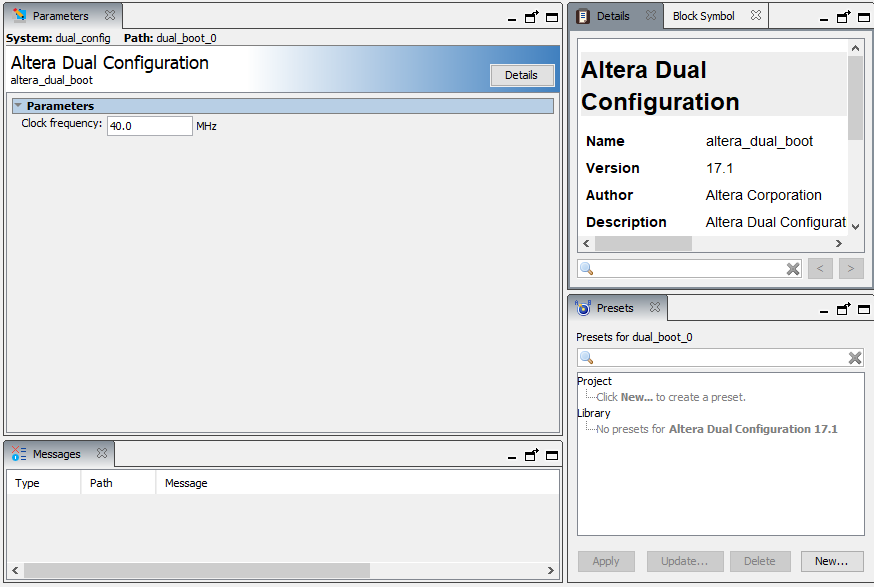
Hi,
the clock frequency is 40 MHz. This is also set in the dual config IP (see attached screenshot).
There is also a design contraint set for the clock
create_generated_clock -name ru_clk -divide_by 2 -master_clock PLL|altpll_component|auto_generated|pll1|clk[1] -source [get_pins -compatibility_mode { *altera_dual_boot:dual_boot_0|alt_dual_boot_avmm:alt_dual_boot_avmm_comp|alt_dual_boot:alt_dual_boot|ru_clk|clk }] [get_pins -compatibility_mode { *altera_dual_boot:dual_boot_0|alt_dual_boot_avmm:alt_dual_boot_avmm_comp|alt_dual_boot:alt_dual_boot|ru_clk|q } ]
- Mark as New
- Bookmark
- Subscribe
- Mute
- Subscribe to RSS Feed
- Permalink
- Report Inappropriate Content
Hi,
How about the host clock frequency that is connected to the dual configuration IP?
- Mark as New
- Bookmark
- Subscribe
- Mute
- Subscribe to RSS Feed
- Permalink
- Report Inappropriate Content
Hi,
you mean the clock that is connected to the clk input of the dual config IP? This is the 40 MHz clock at the output two of the internal PLL.
- Mark as New
- Bookmark
- Subscribe
- Mute
- Subscribe to RSS Feed
- Permalink
- Report Inappropriate Content
Hi,
May I know how do you control the Dual Configuration IP? Is the one that control the dual configuration IP also running 40Mhz? Are you able to share with me your design?
- Mark as New
- Bookmark
- Subscribe
- Mute
- Subscribe to RSS Feed
- Permalink
- Report Inappropriate Content
Hi John,
the dual configuration IP is controlled by a state machine. Both are running at the same 40 MHz clock. The PLL is generating two clocks, the second one is the 40 MHz and is used for the state machine and the dual configuration IP. It is the pll1|clk[1] in the sdc file.
This means the the state of the state machine is updated on the rising edge of the input clock.
Can you tell me if the line in the sdc file is correct?
create_generated_clock -name ru_clk -divide_by 2 -master_clock PLL|altpll_component|auto_generated|pll1|clk[1] -source [get_pins -compatibility_mode { *altera_dual_boot:dual_boot_0|alt_dual_boot_avmm:alt_dual_boot_avmm_comp|alt_dual_boot:alt_dual_boot|ru_clk|clk }] [get_pins -compatibility_mode { *altera_dual_boot:dual_boot_0|alt_dual_boot_avmm:alt_dual_boot_avmm_comp|alt_dual_boot:alt_dual_boot|ru_clk|q } ]
I am sorry but I can't post the source code here in the forum.
I will try to describe the state sequence here. Every item is one state, equals to one clock cycle (25 ns).
(Not named inputs in the states are set to zero)
The inital sequence of the states, that did not work for all devices...
- ...
- avmm_rcv_address="000", avmm_rcv_writedata(0)='1', avmm_rcv_write='0'
- avmm_rcv_address="000", avmm_rcv_writedata(0)='1', avmm_rcv_write='1'
- avmm_rcv_address="011", avmm_rcv_read='1'
- avmm_rcv_address="011", avmm_rcv_read='1' (avmm_rcv_readdata(0) is checked here, but because it is always zero, it makes no difference if it is checked or not)
- avmm_rcv_address="010", avmm_rcv_writedata(idx)='1', avmm_rcv_write='0' where idx is 0 to 3
- avmm_rcv_address="010", avmm_rcv_writedata(idx)='1', avmm_rcv_write='1' where idx is 0 to 3 and of course the same value as in the state before
- avmm_rcv_address="011", avmm_rcv_read='1'
- avmm_rcv_address="011", avmm_rcv_read='1', repeat this state till avmm_rcv_readdata(0)='0'
- ...
What leads to the same result, as checking the busy flag (does not work for all devices)
- ...
- avmm_rcv_address="000", avmm_rcv_writedata(0)='1', avmm_rcv_write='0'
- avmm_rcv_address="000", avmm_rcv_writedata(0)='1', avmm_rcv_write='1'
- IDLE state (all set to zero)
- IDLE state
- avmm_rcv_address="010", avmm_rcv_writedata(idx)='1', avmm_rcv_write='0' where idx is 0 to 3
- avmm_rcv_address="010", avmm_rcv_writedata(idx)='1', avmm_rcv_write='1' where idx is 0 to 3 and of course the same value as in the state before
- avmm_rcv_address="011", avmm_rcv_read='1'
- avmm_rcv_address="011", avmm_rcv_read='1', repeat this state till avmm_rcv_readdata(0)='0'
- ...
What seems to work
- ...
- avmm_rcv_address="000", avmm_rcv_writedata(0)='1', avmm_rcv_write='0'
- avmm_rcv_address="000", avmm_rcv_writedata(0)='1', avmm_rcv_write='1'
- IDLE state (all set to zero)
- IDLE state
- IDLE state
- avmm_rcv_address="010", avmm_rcv_writedata(idx)='1', avmm_rcv_write='0' where idx is 0 to 3
- avmm_rcv_address="010", avmm_rcv_writedata(idx)='1', avmm_rcv_write='1' where idx is 0 to 3 and of course the same value as in the state before
- avmm_rcv_address="011", avmm_rcv_read='1'
- avmm_rcv_address="011", avmm_rcv_read='1', repeat this state till avmm_rcv_readdata(0)='0'
- ...
What does not work for any of the devices
- ...
- avmm_rcv_address="000", avmm_rcv_writedata(0)='1', avmm_rcv_write='0'
- avmm_rcv_address="000", avmm_rcv_writedata(0)='1', avmm_rcv_write='1'
- IDLE state (all set to zero)
- avmm_rcv_address="010", avmm_rcv_writedata(idx)='1', avmm_rcv_write='0' where idx is 0 to 3
- avmm_rcv_address="010", avmm_rcv_writedata(idx)='1', avmm_rcv_write='1' where idx is 0 to 3 and of course the same value as in the state before
- avmm_rcv_address="011", avmm_rcv_read='1'
- avmm_rcv_address="011", avmm_rcv_read='1', repeat this state till avmm_rcv_readdata(0)='0'
- ...
- Mark as New
- Bookmark
- Subscribe
- Mute
- Subscribe to RSS Feed
- Permalink
- Report Inappropriate Content
Hi,
I would suspect that the state machine is causing the issue. Not sure if you are able to use the workaround that is working for all the board?
- Subscribe to RSS Feed
- Mark Topic as New
- Mark Topic as Read
- Float this Topic for Current User
- Bookmark
- Subscribe
- Printer Friendly Page