- Mark as New
- Bookmark
- Subscribe
- Mute
- Subscribe to RSS Feed
- Permalink
- Report Inappropriate Content
I am doing remote update and want to set watchdog value.
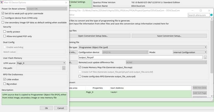
1.How to set watchdog value for reconfiguration of MAX10 in Quartus software?
I chose Dual compressed images mode but watchdog is still disabled.The checkbox is disabled and I can't enable it.
2. If I choose compiling my project using script(shell command) instead of Quartus software , then How to set watchdog value for reconfiguration of MAX10 ? Hope for your specific steps and statements.
Link Copied
- Mark as New
- Bookmark
- Subscribe
- Mute
- Subscribe to RSS Feed
- Permalink
- Report Inappropriate Content
I'm not sure if this enables the option, but you currently only have one .sof data page in the "Input files to convert" section. There's no reason to have a watchdog to switch to a different image if only one image is available. Try adding the second .sof page and see if that enables the option. You can also check out this training for more info on this:
https://www.intel.com/content/www/us/en/programmable/support/training/course/omaxrsu.html
#iwork4intel
- Mark as New
- Bookmark
- Subscribe
- Mute
- Subscribe to RSS Feed
- Permalink
- Report Inappropriate Content
Thanks very much @sstrell. What you saidis a big help. It can enalbe this option by adding another page.
By the way, if I choose compiling my project using script(shell command) instead of Quartus software , then How to set watchdog value for reconfiguration of MAX10 ? Hope for your specific steps and statements. Thanks very much!
- Mark as New
- Bookmark
- Subscribe
- Mute
- Subscribe to RSS Feed
- Permalink
- Report Inappropriate Content
Hi
Thanks very much!
I have another question here:
I can only config the high 12bits of watchdog value. Then the default value below is 0x1FFF. It is 16bits and exceeds 12bits, so what's the actual value to be given the watchdog with the default 0x1FFF? ( what's the number of watchdog timer value(decimal) in the fomular at the bottom of the picture? )

- Mark as New
- Bookmark
- Subscribe
- Mute
- Subscribe to RSS Feed
- Permalink
- Report Inappropriate Content
Hi KWang97,
Watchdog at Convert Programming file is enabled after adding x2 .sof page with two designs that compiled with Dual Compressed Internal Images.

The counter is 29 bits wide and has a maximum count value of 2^29.

However, you can only specify what the timeout value should be to a granularity of 17 bits by entering a 12-bit value, representing the 12 most significant bits of the counter.
You can only specify the most significant 12 bits (red circle below)

0x1fff represent the most significant 12 bits that you can specify/change.

I hope it's clear and help you.
Thanks
- Mark as New
- Bookmark
- Subscribe
- Mute
- Subscribe to RSS Feed
- Permalink
- Report Inappropriate Content
Hi WolfGang
Thanks for your explanation very much. I am just confused with 12bits MSB, while I think 0x1fff has 13bits instead of 12bits. Does 12bits MSB not include bit0?
Another question: What's the watchdog timer frequency when caculating the timeout? How to determine it? The input clock of my Dual_config IP is 50MHz.
Thanks!
- Mark as New
- Bookmark
- Subscribe
- Mute
- Subscribe to RSS Feed
- Permalink
- Report Inappropriate Content
Hi KWang97,
12bits MSB starting from bit18-bit29 (refer to picture above).
For User Watchdog Internal Circuitry Timing Specifications, you may refer to the following link:
https://www.intel.com/content/www/us/en/programmable/documentation/mcn1397700832153.html#mcn1398080260173
Thanks!
- Mark as New
- Bookmark
- Subscribe
- Mute
- Subscribe to RSS Feed
- Permalink
- Report Inappropriate Content
Add: The device I use is : 10M08SAU327I7G with 25MHz input oscillator. While I use pll IP to get 50MHz clock to my Dual_config.
- Mark as New
- Bookmark
- Subscribe
- Mute
- Subscribe to RSS Feed
- Permalink
- Report Inappropriate Content
Hi,@ShafiqY_Intel
Could you please help me with a further question. This issue is emergency for me, so I hope you could help me. Thanks very much!
How to make a file with 16 bytes's data content that can be programmed into user flash?
Each of our product will have a unique serial number which is 4 bytes long, like 0x"0F0F0F0F". The number will be written into FPGA in our product. But the serial number will be modified for different products when they leave factory. FPGA in the product will read this serial numer when the product operates in customer's place. How can I realize this?
My initial idea is like below:
( I make a file whose content can be edited. The file is edited with 4 bytes's serial number. Then this file can be downloaded into UFM and FPGA could read the serial number from UFM.
But how will I make such a file that can be edited and be programmed into UFM with Jtag or other ways?)
Besides that, are there any other good ways to realize this function except what I proposed? If not, please tell me how to realize the function I proposed.
Thanks very much!
- Mark as New
- Bookmark
- Subscribe
- Mute
- Subscribe to RSS Feed
- Permalink
- Report Inappropriate Content
Hi KWang97,

For UFM Content Initialization, you can use either:
- On-Chip Flash Intel FPGA IP core.
- Convert Programming File tool
On-Chip Flash Intel FPGA IP core.

Convert Programming File tool

Hope this will help.
Thanks
- Mark as New
- Bookmark
- Subscribe
- Mute
- Subscribe to RSS Feed
- Permalink
- Report Inappropriate Content
Thanks for your idea. While The problem is that workers in factory can’t compile. They just can program a file into FPGA.
They will edit a file with different serial number to each product and then program the file into FPGA.
Is there a method that I can edit a file and then directly program the file into FPGA without compiling. Thanks!
. The serial number will be set by workers in the factory ,then they can only program a file with serial number into FPGA. This will be done independently with the application pof. The worker in factory can't compile FPGA project and they can only do the programming with Jtag. So they just modify the file and download this file directly into UFM. So how will this be realized. Thanks very much!
- Mark as New
- Bookmark
- Subscribe
- Mute
- Subscribe to RSS Feed
- Permalink
- Report Inappropriate Content
Yes, you're right. Modify the file and program directly into UFM.
I hope you can move forward with your design.
Thank you for choosing and trust our product. :)
- Subscribe to RSS Feed
- Mark Topic as New
- Mark Topic as Read
- Float this Topic for Current User
- Bookmark
- Subscribe
- Printer Friendly Page