- Mark as New
- Bookmark
- Subscribe
- Mute
- Subscribe to RSS Feed
- Permalink
- Report Inappropriate Content
We had an external ADC connected to a MAX10 (10M50). To investigate the signal integrity of the signals between the MAX10 and ADC, eye diagrams of various signals were recorded. We noticed a bit strange behavior with the output driver of the MAX10.
The output signal (output strength set to LVCMOS 2mA) of the MAX10 is shown in the picture TC73_02_ADC_clock_amp_1_2.png. What we noticed are the levels in the output signal of the MAX10. Whereas the output signal of the external ADC (picture TC73_02_ADC_SDOA_amp_1_2.png) looks as expected.
Is there an explanation for these levels in the output signal (rising and falling edge) of the MAX10 driver
Link Copied
- Mark as New
- Bookmark
- Subscribe
- Mute
- Subscribe to RSS Feed
- Permalink
- Report Inappropriate Content
Hi,
The images are missing. Can you please attach them?
Regards.
- Mark as New
- Bookmark
- Subscribe
- Mute
- Subscribe to RSS Feed
- Permalink
- Report Inappropriate Content
Sorry,
here they are, hopefully
- Mark as New
- Bookmark
- Subscribe
- Mute
- Subscribe to RSS Feed
- Permalink
- Report Inappropriate Content
I am little confused on the query here. You said, an external ADC was connected to MAX 10. So, ADC output is becomes an input to MAX 10, right? Are you checking at the MAX 10 input pin?
- Mark as New
- Bookmark
- Subscribe
- Mute
- Subscribe to RSS Feed
- Permalink
- Report Inappropriate Content
Sorry for my imprecise wording.
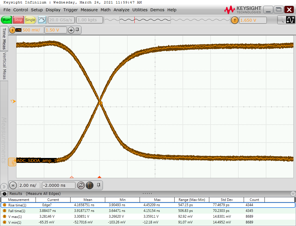
The picture "TC73_02_ADC_clock_amp_1_2.png" shows an output of the MAX10, here the clock signal to the ADC (input signal for ADC), with the mentioned levels in the signal curve.
For comparison, "TC73_02_ADC_SDOA_amp_1_2.png" shows the output signal of the ADC (input signal for MAX10), which has no levels in the output signals.
These levels in the output of the MAX10 have been observed on many of the recorded eye diagrams.
- Mark as New
- Bookmark
- Subscribe
- Mute
- Subscribe to RSS Feed
- Permalink
- Report Inappropriate Content
Looks like this thread was left unattended. Sorry about that. Not sure, if you still need the support, but putting my thoughts here.
As the output is LVCMOS, there could be a chance that the signal strength is not enough. You can try increasing the strength.
Regards
- Mark as New
- Bookmark
- Subscribe
- Mute
- Subscribe to RSS Feed
- Permalink
- Report Inappropriate Content
This thread will be transitioned to community support. If you have a new question, feel free to open a new thread to get the support from Intel experts. Otherwise, the community users will continue to help you on this thread. Thank you
- Subscribe to RSS Feed
- Mark Topic as New
- Mark Topic as Read
- Float this Topic for Current User
- Bookmark
- Subscribe
- Printer Friendly Page