- Mark as New
- Bookmark
- Subscribe
- Mute
- Subscribe to RSS Feed
- Permalink
- Report Inappropriate Content
Well, I can't hide that I'm a bit scared. This is my 1st FPGA design and I'm doing it without having the MAX 10 here to test first.
I know that I might be asking too much :) but do you guys see anything wrong with the FPGA connections on my schematics? It's the MAX 10 10M02 144-pin EQFP package (10M02SCE144C8G). Disregard the banks 3,5,6,8 on the bottom half. Those have the project-specific nets. My main concerns are with the JTAG port, power and clock input: https://alteraforum.com/forum/attachment.php?attachmentid=14072&stc=1
Link Copied
- Mark as New
- Bookmark
- Subscribe
- Mute
- Subscribe to RSS Feed
- Permalink
- Report Inappropriate Content
You must have pull-ups on nSTATUS and CONF_DONE, else it won't boot. Long-standing tip, applies to most Altera families...
- Mark as New
- Bookmark
- Subscribe
- Mute
- Subscribe to RSS Feed
- Permalink
- Report Inappropriate Content
Basically O.K., but you should consider the connection guidelines for pins nCONFIG, nSTATUS, CONF_DONE (pull-up) and CONFIG_SEL (pull-down).
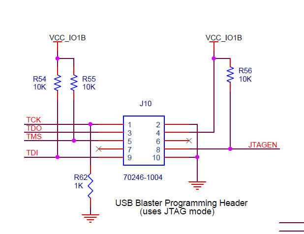
JTAGEN is correctly wired with a pull-up, but I don't see the purpose of connecting it to JTAG header pin 8.- Mark as New
- Bookmark
- Subscribe
- Mute
- Subscribe to RSS Feed
- Permalink
- Report Inappropriate Content
This document is a useful checklist for new designs:
https://www.altera.com/en_us/pdfs/literature/dp/max-10/pcg-01018.pdf (https://www.altera.com/en_us/pdfs/literature/dp/max-10/pcg-01018.pdf) CONFIG_SEL can be safely ignored (just used as another I/O) on the small devices with only one configuration. nCONFIG must however be pulled or tied high - forgot that one in my earlier post.- Mark as New
- Bookmark
- Subscribe
- Mute
- Subscribe to RSS Feed
- Permalink
- Report Inappropriate Content
--- Quote Start --- JTAGEN is correctly wired with a pull-up, but I don't see the purpose of connecting it to JTAG header pin 8. --- Quote End --- Well, connecting JTAGEN to pin 8 of the JTAG header was simply copying from the MAX 10 evaluation board schematics: https://alteraforum.com/forum/attachment.php?attachmentid=14076&stc=1 But I guess since I'm not using the JTAG pins for anything else other than the dedicated JTAG functions I could simply leave it with the pullup.
- Mark as New
- Bookmark
- Subscribe
- Mute
- Subscribe to RSS Feed
- Permalink
- Report Inappropriate Content
As for the other pins, thank you guys very much for pointing that out. I'd have completely missed those.
Here's how it looks now: https://alteraforum.com/forum/attachment.php?attachmentid=14078&stc=1&d=1503765796"]https://alteraforum.com/forum/attachment.php?attachmentid=14078&stc=1&d=1503765796 CONFIG_SEL is left open as you mentioned. The MAX 10 Pin Connection Guidelines does indeed say: if you disable the “auto-reconfigure from secondary image when initial image fails” option in the quartus prime softwarewhen generating the pof file, the fpga will always load the configuration image 0 without sampling the physical
config_sel pin during power up. And the JTAGEN pin is simply pulled up and not connected to pin 8 of the connector, since the JTAG pins are not being used for anything else other than JTAG. I'm using 1.5k and 12k resistors for the pull ups and pull downs, and not the values suggested by the Altera documentation. I don't see this being critical, and I'm only doing it like this because 1.5k and 12k are the closest resistor values already in use on my board. But is there any possible issues with that?
- Mark as New
- Bookmark
- Subscribe
- Mute
- Subscribe to RSS Feed
- Permalink
- Report Inappropriate Content
Pull-up values don't seem to be critical.
- Mark as New
- Bookmark
- Subscribe
- Mute
- Subscribe to RSS Feed
- Permalink
- Report Inappropriate Content
The FPGA clock is at 50MHz, and the fastest signal coming out of the FPGA will be at most 10MHz. Do I need to worry about termination, parallel traces, ground planes (running certain traces adjacent to ground planes for return path impedance matching), or even trace lengths if the longest is ~2cm?
I am keeping clock signals short and as away as possible from other traces, not worrying that much about data signals, and not doing termination at all, with the understanding that 10MHz is nothing to worry that much about.- Subscribe to RSS Feed
- Mark Topic as New
- Mark Topic as Read
- Float this Topic for Current User
- Bookmark
- Subscribe
- Printer Friendly Page