- Mark as New
- Bookmark
- Subscribe
- Mute
- Subscribe to RSS Feed
- Permalink
- Report Inappropriate Content
Hi all,
I am trying to figure out what I am doing wrong with simulations involving Altera IP.... Below is my incredibly simple design to show off the issue I am having. I pipe a clock into a PLL generated through the wizard, and watch the clock and locked outputs. As you can see from the simulation the lock remains low, and the clock output is in an unknown state. I don't see any warnings or errors in modelsim. Any help would be greatly appreciated.
library ieee;
use ieee.std_logic_1164.all;
entity top is
    port
    (
        inclk0        : in std_logic;
        c0    : out std_logic;
        locked        : out std_logic
    );
end entity;
architecture rtl of top is
    component pll0
        PORT
        (
            inclk0        : IN STD_LOGIC  := '0';
            c0        : OUT STD_LOGIC ;
            locked        : OUT STD_LOGIC
        );
    end component;
begin
    pll0_inst : pll0 PORT MAP (
            inclk0     => inclk0,
            c0     => c0,
            locked     => locked
        );
end rtl;
https://alteraforum.com/forum/attachment.php?attachmentid=14807&stc=1
Link Copied
- Mark as New
- Bookmark
- Subscribe
- Mute
- Subscribe to RSS Feed
- Permalink
- Report Inappropriate Content
Can you even synthesize the design in Quartus? Perhaps the PLL IP was not generated correctly or you didn't generate simulation model files. Did you make sure that the simulation model is getting compiled in ModelSim?
- Mark as New
- Bookmark
- Subscribe
- Mute
- Subscribe to RSS Feed
- Permalink
- Report Inappropriate Content
Hi,
Are you using testbench? Can you attach the transcript of Modelsim? Best Regards, Anand Raj Shankar (This message was posted on behalf of Intel Corporation)- Mark as New
- Bookmark
- Subscribe
- Mute
- Subscribe to RSS Feed
- Permalink
- Report Inappropriate Content
I got past the PLL issue
My problem now is with the modular adc simulation. I used the wizard to configure the ADC, include the .qip and .sip files in the project as suggested by the prompt. When I go to simulate I get this:
vcom -reportprogress 300 -work work /home/swinchen/quartus/robot_board_test/robot_board_tb.vhd#  Model Technology ModelSim - Intel FPGA Edition vcom 10.5b Compiler 2016.10 Oct  5 2016#  Start time: 10:25:41 on Feb 09,2018#  vcom -reportprogress 300 -work work /home/swinchen/quartus/robot_board_test/robot_board_tb.vhd #  -- Loading package STANDARD#  -- Loading package TEXTIO#  -- Loading package std_logic_1164#  -- Loading package NUMERIC_STD#  -- Compiling entity robot_board_tb#  -- Compiling architecture rtl of robot_board_tb#  End time: 10:25:41 on Feb 09,2018, Elapsed time: 0:00:00#  Errors: 0, Warnings: 0
vsim work.robot_board_tb#  vsim work.robot_board_tb #  Start time: 10:25:50 on Feb 09,2018#  Loading std.standard#  Loading std.textio(body)#  Loading ieee.std_logic_1164(body)#  Loading ieee.numeric_std(body)#  Loading work.robot_board_tb(rtl)#  Loading altera_mf.altera_mf_components#  Loading work.robot_board(rtl)#  Loading ieee.std_logic_arith(body)#  Loading ieee.std_logic_unsigned(body)#  Loading altera_mf.altera_common_conversion(body)#  Loading altera_mf.altera_device_families(body)#  Loading altera_mf.altsyncram(translated)#  Loading work.pll(syn)#  Loading altera_mf.mf_pllpack(body)#  Loading altera_mf.altpll(behavior)#  Loading altera_mf.mf_cycloneiii_pll(vital_pll)#  Loading altera_mf.mf_cda_mn_cntr(behave)#  Loading altera_mf.mf_cda_scale_cntr(behave)#  Loading work.adc_controller(rtl)#  Loading work.adc_core(rtl)#  ** Warning: (vsim-3473) Component instance "modular_adc_0 : adc_core_modular_adc_0" is not bound.#     Time: 0 ps  Iteration: 0  Instance: /robot_board_tb/dut/adc_inst File: /home/swinchen/quartus/robot_board_test/adc_core/simulation/adc_core.vhd#  Loading work.slave_spi_interface(rtl)#  ** Warning: Design size of 17430 statements exceeds ModelSim-Intel FPGA Starter Edition recommended capacity.#  Expect performance to be adversely affected.#  ** Warning: (vsim-8684) No drivers exist on out port /robot_board_tb/dut/adc_inst/command_ready, and its initial value is not used.#  Therefore, simulation behavior may occur that is not in compliance with#  the VHDL standard as the initial values come from the base signal /robot_board_tb/dut/command_ready.#  ** Warning: (vsim-8684) No drivers exist on out port /robot_board_tb/dut/adc_inst/response_valid, and its initial value is not used.#  Therefore, simulation behavior may occur that is not in compliance with#  the VHDL standard as the initial values come from the base signal /robot_board_tb/dut/adc_ram_wr_en.#  ** Warning: (vsim-8684) No drivers exist on out port /robot_board_tb/dut/adc_inst/response_channel(4), and its initial value is not used.#  Therefore, simulation behavior may occur that is not in compliance with#  the VHDL standard as the initial values come from the base signal /robot_board_tb/dut/adc_ram_wr_chsel(4).#  ** Warning: (vsim-8684) No drivers exist on out port /robot_board_tb/dut/adc_inst/response_channel(3 downto 0), and its initial value is not used.#  Therefore, simulation behavior may occur that is not in compliance with#  the VHDL standard as the initial values come from the base signal /robot_board_tb/dut/adc_ram_wr_chsel(3 downto 0).#  ** Warning: (vsim-8684) No drivers exist on out port /robot_board_tb/dut/adc_inst/response_data, and its initial value is not used.#  Therefore, simulation behavior may occur that is not in compliance with#  the VHDL standard as the initial values come from the base signal /robot_board_tb/dut/adc_ram_wr_data.
I am not sure how to get rid of the # ** Warning: (vsim-3473) Component instance "modular_adc_0 : adc_core_modular_adc_0" is not bound.. Any suggestions?
- Mark as New
- Bookmark
- Subscribe
- Mute
- Subscribe to RSS Feed
- Permalink
- Report Inappropriate Content
I tried including the "modular_adc_0" library and get this:
#  Loading modular_adc_0.adc_core_modular_adc_0
#  ** Error: (vsim-3033) /home/swinchen/quartus/robot_board_test/adc_core/simulation/submodules/adc_core_modular_adc_0.v(26): Instantiation of 'adc_core_modular_adc_0_control_internal' failed. The design unit was not found.
#     Time: 0 ps  Iteration: 0  Instance: /robot_board_tb/dut/adc_inst/modular_adc_0 File: /home/swinchen/quartus/robot_board_test/adc_core/simulation/submodules/adc_core_modular_adc_0.v
#          Searched libraries:
#              /home/swinchen/quartus/robot_board_test/simulation/modelsim/robot_board_test_iputf_libs/modular_adc_0
#              /home/swinchen/quartus/robot_board_test/simulation/modelsim/rtl_work
#  Loading work.slave_spi_interface(rtl)
#  Error loading design
#  End time: 10:57:09 on Feb 09,2018, Elapsed time: 0:00:00
#  Errors: 1, Warnings: 0
- Mark as New
- Bookmark
- Subscribe
- Mute
- Subscribe to RSS Feed
- Permalink
- Report Inappropriate Content
Hi,
May be because of compilation order,component interface declaration. If you compile each file separately and you have to compile from the bottom up. or Use script to setup environment which is generated during design. Threads addressing same issue http://www.alteraforum.com/forum/showthread.php?t=36720 https://www.alteraforum.com/forum/showthread.php?t=53077 Best Regards, Anand Raj Shankar (This message was posted on behalf of Intel Corporation)- Mark as New
- Bookmark
- Subscribe
- Mute
- Subscribe to RSS Feed
- Permalink
- Report Inappropriate Content
Those threads do not appear to have solutions.
What is the name of the script that is generated during the design? I believe modelsim is running this script (simulation/modelsim/robot_board_test_run_msim_rtl_vhdl.do):
transcript on
if ! {
	file mkdir robot_board_test_iputf_libs
}
if {} {
	vdel -lib rtl_work -all
}
vlib rtl_work
vmap work rtl_work
# ##### Libraries for IPUTF cores
vlib robot_board_test_iputf_libs/control_internal
vmap control_internal ./robot_board_test_iputf_libs/control_internal
vlib robot_board_test_iputf_libs/modular_adc_0
vmap modular_adc_0 ./robot_board_test_iputf_libs/modular_adc_0
# ##### End libraries for IPUTF cores
# ##### MIF file copy and HDL compilation commands for IPUTF cores
vlog "/home/swinchen/quartus/robot_board_test/adc_core/simulation/submodules/altera_modular_adc_control.v"             -work control_internal
vlog "/home/swinchen/quartus/robot_board_test/adc_core/simulation/submodules/altera_modular_adc_control_avrg_fifo.v"   -work control_internal
vlog "/home/swinchen/quartus/robot_board_test/adc_core/simulation/submodules/altera_modular_adc_control_fsm.v"         -work control_internal
vlog "/home/swinchen/quartus/robot_board_test/adc_core/simulation/submodules/chsel_code_converter_sw_to_hw.v"          -work control_internal
vlog "/home/swinchen/quartus/robot_board_test/adc_core/simulation/submodules/fiftyfivenm_adcblock_primitive_wrapper.v" -work control_internal
vlog "/home/swinchen/quartus/robot_board_test/adc_core/simulation/submodules/fiftyfivenm_adcblock_top_wrapper.v"       -work control_internal
vlog "/home/swinchen/quartus/robot_board_test/adc_core/simulation/submodules/adc_core_modular_adc_0.v"                 -work modular_adc_0
vcom "/home/swinchen/quartus/robot_board_test/adc_core/simulation/adc_core.vhd"
vlog -vlog01compat -work work +incdir+/home/swinchen/quartus/robot_board_test/db {/home/swinchen/quartus/robot_board_test/db/pll_altpll.v}
vcom -93 -work work {/home/swinchen/quartus/robot_board_test/slave_spi_interface.vhd}
vcom -93 -work work {/home/swinchen/quartus/robot_board_test/robot_board.vhd}
vcom -93 -work work {/home/swinchen/quartus/robot_board_test/adc_controller.vhd}
vcom -93 -work work {/home/swinchen/quartus/robot_board_test/pll.vhd}
vcom -93 -work work {/home/swinchen/quartus/robot_board_test/robot_board_tb.vhd}
vsim -t 1ps -L altera -L lpm -L sgate -L altera_mf -L altera_lnsim -L fiftyfivenm -L fiftyfivenm_ver -L rtl_work -L work -L control_internal -L modular_adc_0 -voptargs="+acc"  robot_board_tb
do /home/swinchen/quartus/robot_board_test/adc_core/simulation/mentor/msim_setup.tcl
Are you saying that the msim_setup.tcl should be executed first?
- Mark as New
- Bookmark
- Subscribe
- Mute
- Subscribe to RSS Feed
- Permalink
- Report Inappropriate Content
Hi,
--- Quote Start --- Are you saying that the msim_setup.tcl should be executed first? --- Quote End --- Yes, DO you have license? The warning may be generated because of license. Best Regards, Anand Raj Shankar (This message was posted on behalf of Intel Corporation)https://www.alteraforum.com/forum/attachment.php?attachmentid=14820
- Mark as New
- Bookmark
- Subscribe
- Mute
- Subscribe to RSS Feed
- Permalink
- Report Inappropriate Content
What would I need for a license? I am using Quartus Prime Lite 17.1. My design is relatively small and I don't get any warnings/errors about exceeding the 10,000 LOC limit.
Thanks, - Sam- Mark as New
- Bookmark
- Subscribe
- Mute
- Subscribe to RSS Feed
- Permalink
- Report Inappropriate Content
Hi,
It's not related to license. 1.Use the msim_setup.tcl for simulation which help us to load all the necessary libraries. 2.And also follow the steps given in msim_setup.tcl which will eliminate the warning. The image which i have attached previously,There i tried to loaded the libraries manually which generated the warning. Now i have simulated the same project using script which eliminated the warning. So this warning may be related to libraries and compilation order. Let me know if this has helped resolve the issue you are facing or if you need any further assistance. Best Regards, Anand Raj Shankar (This message was posted on behalf of Intel Corporation) https://www.alteraforum.com/forum/attachment.php?attachmentid=14839
- Mark as New
- Bookmark
- Subscribe
- Mute
- Subscribe to RSS Feed
- Permalink
- Report Inappropriate Content
I think I'm having the same problem with ALTPLL RTL simulation. I have to believe this is something simple, but I'm not getting the PLL to put out a clock.
Testbench code: `timescale 1ns / 1ps module TB_1(); // Inputs reg ClkIN; reg ResetN; wire [3:0] SignalOut; testpll testpll( .ClkIN(ClkIN), .ResetN(ResetN), .SignalOut(SignalOut) ); initial begin ClkIN = 1'b0; # 5 ClkIN = 1'b1; forever begin //Create a 25MHz clock # 20 ClkIN = !ClkIN; end end initial begin $display($time, " << Starting Simulation >> "); # 1 ResetN = 1'b1; //Apply Reset twice # 150 ResetN = 1'b0; # 1500 ResetN = 1'b1; # 1500 ResetN = 1'b0; # 1500 ResetN = 1'b1; # 1000; $display($time, "<< Simulation Complete >>"); // $stop; end endmodule No errors or warnings in modelsim. I have attached a couple of screencaps of the waveforms. There should be plenty of time to lock. FPGA code: module testpll ( ClkIN, ResetN, SignalOut ); input ClkIN; input ResetN; output [3:0] SignalOut; reg [3:0] SignalOut; wire SysClk; always @ (posedge SysClk or negedge ResetN) begin if (!ResetN) begin SignalOut <= 0; end else begin SignalOut <= SignalOut+1; //simple 4-bit free-running counter w/ ACLR end end //end always /* * PLL block instantiation. Take in 25 MHz clock and generate internal 135 MHz clock */ Imelda_PLL Imelda_PLL( .areset ( !ResetN ), .inclk0 ( ClkIN ), .c0 ( SysClk ), .locked () ); endmodule The PLL is from the project that I originally had the issue with, so I cut it down to this simple example. The PLL simply takes in 25 MHz and cranks it up to 135 MHz. I can zip the folder and send it if you like. This is targeted to a 10CL006-8 in TQFP. Quartus Prime Lite Edition V17.1.1 Build 593 12/11/2017 Any thoughts or suggestions? Until I have a clock it's kinda tough to do much simulation. Thanks much Chip Brownhttps://alteraforum.com/forum/attachment.php?attachmentid=14908&stc=1 https://alteraforum.com/forum/attachment.php?attachmentid=14909&stc=1- Mark as New
- Bookmark
- Subscribe
- Mute
- Subscribe to RSS Feed
- Permalink
- Report Inappropriate Content
Hi,
When you generated the ALTPLL core, did you use the reset pin and what is the setting for the reset ( PLLs can be reset internally or via external reset pin). If you have used reset internally, the reset logic will be added internally and PLL will auto-reset itself on Power-on. If using external reset , you will have to provide the reset controls as you've already done. During simulations, have you also included the device specific simulation libraries for the PLLs? - Abr- Mark as New
- Bookmark
- Subscribe
- Mute
- Subscribe to RSS Feed
- Permalink
- Report Inappropriate Content
I have tried the PLL with and without the "Enable self-reset on loss lock" check. No difference. I tried adding a pfdena input tied to 1'b1 and !ResetN - no difference.
What seems most strange to me is that the simulation shows the c0 output in the HiZ state. I don't understand what's in that block, but I would not expect it to be HiZ ever. I will submit a support case and see if I can send the testpll folder for you to look at. Service request# 11384121 This is the output I get from modelsim: # Reading C:/intelFPGA_lite/17.1/modelsim_ase/tcl/vsim/pref.tcl# do testpll_run_msim_rtl_verilog.do# if {[file exists rtl_work]} {# vdel -lib rtl_work -all# }# vlib rtl_work# vmap work rtl_work# Model Technology ModelSim - Intel FPGA Edition vmap 10.5b Lib Mapping Utility 2016.10 Oct 5 2016# vmap work rtl_work # Copying C:/intelFPGA_lite/17.1/modelsim_ase/win32aloem/../modelsim.ini to modelsim.ini# Modifying modelsim.ini# # vlog -vlog01compat -work work +incdir+C:/projects/Imelda/FPGA/Imelda_Altera_10CL006_testpll/source {C:/projects/Imelda/FPGA/Imelda_Altera_10CL006_testpll/source/testpll_20180302.v}# Model Technology ModelSim - Intel FPGA Edition vlog 10.5b Compiler 2016.10 Oct 5 2016# Start time: 10:25:41 on Mar 02,2018# vlog -reportprogress 300 -vlog01compat -work work "+incdir+C:/projects/Imelda/FPGA/Imelda_Altera_10CL006_testpll/source" C:/projects/Imelda/FPGA/Imelda_Altera_10CL006_testpll/source/testpll_20180302.v # -- Compiling module testpll# # Top level modules:# testpll# End time: 10:25:41 on Mar 02,2018, Elapsed time: 0:00:00# Errors: 0, Warnings: 0# vlog -vlog01compat -work work +incdir+C:/projects/Imelda/FPGA/Imelda_Altera_10CL006_testpll/ALTPLL {C:/projects/Imelda/FPGA/Imelda_Altera_10CL006_testpll/ALTPLL/testpll_altpll.v}# Model Technology ModelSim - Intel FPGA Edition vlog 10.5b Compiler 2016.10 Oct 5 2016# Start time: 10:25:41 on Mar 02,2018# vlog -reportprogress 300 -vlog01compat -work work "+incdir+C:/projects/Imelda/FPGA/Imelda_Altera_10CL006_testpll/ALTPLL" C:/projects/Imelda/FPGA/Imelda_Altera_10CL006_testpll/ALTPLL/testpll_altpll.v # -- Compiling module testpll_altpll# # Top level modules:# testpll_altpll# End time: 10:25:41 on Mar 02,2018, Elapsed time: 0:00:00# Errors: 0, Warnings: 0# vlog -vlog01compat -work work +incdir+C:/projects/Imelda/FPGA/Imelda_Altera_10CL006_testpll/db {C:/projects/Imelda/FPGA/Imelda_Altera_10CL006_testpll/db/testpll_altpll_altpll.v}# Model Technology ModelSim - Intel FPGA Edition vlog 10.5b Compiler 2016.10 Oct 5 2016# Start time: 10:25:41 on Mar 02,2018# vlog -reportprogress 300 -vlog01compat -work work "+incdir+C:/projects/Imelda/FPGA/Imelda_Altera_10CL006_testpll/db" C:/projects/Imelda/FPGA/Imelda_Altera_10CL006_testpll/db/testpll_altpll_altpll.v # -- Compiling module testpll_altpll_altpll# # Top level modules:# testpll_altpll_altpll# End time: 10:25:41 on Mar 02,2018, Elapsed time: 0:00:00# Errors: 0, Warnings: 0# # vlog -vlog01compat -work work +incdir+C:/projects/Imelda/FPGA/Imelda_Altera_10CL006_testpll/simulation/source {C:/projects/Imelda/FPGA/Imelda_Altera_10CL006_testpll/simulation/source/TB_1_20180301.v}# Model Technology ModelSim - Intel FPGA Edition vlog 10.5b Compiler 2016.10 Oct 5 2016# Start time: 10:25:41 on Mar 02,2018# vlog -reportprogress 300 -vlog01compat -work work "+incdir+C:/projects/Imelda/FPGA/Imelda_Altera_10CL006_testpll/simulation/source" C:/projects/Imelda/FPGA/Imelda_Altera_10CL006_testpll/simulation/source/TB_1_20180301.v # -- Compiling module TB_1# # Top level modules:# TB_1# End time: 10:25:41 on Mar 02,2018, Elapsed time: 0:00:00# Errors: 0, Warnings: 0# # vsim -t 1ps -L altera_ver -L lpm_ver -L sgate_ver -L altera_mf_ver -L altera_lnsim_ver -L cyclone10lp_ver -L rtl_work -L work -voptargs="+acc" TB_1# vsim -t 1ps -L altera_ver -L lpm_ver -L sgate_ver -L altera_mf_ver -L altera_lnsim_ver -L cyclone10lp_ver -L rtl_work -L work -voptargs=""+acc"" TB_1 # Start time: 10:25:41 on Mar 02,2018# Loading work.TB_1# Loading work.testpll# Loading work.testpll_altpll# Loading altera_mf_ver.altpll# Loading altera_mf_ver.ALTERA_DEVICE_FAMILIES# Loading altera_mf_ver.pll_iobuf# # add wave *# view structure# .main_pane.structure.interior.cs.body.struct# view signals# .main_pane.objects.interior.cs.body.tree# run -all# 0 << Starting Simulation >> # 5651<< Simulation Complete >> restart -f add wave -position end sim:/TB_1/testpll/testPLL/areset add wave -position end sim:/TB_1/testpll/testPLL/pfdena add wave -position end sim:/TB_1/testpll/testPLL/inclk0 add wave -position end sim:/TB_1/testpll/testPLL/locked add wave -position end sim:/TB_1/testpll/testPLL/c0 run -all# 0 << Starting Simulation >> # 5651<< Simulation Complete >> https://alteraforum.com/forum/attachment.php?attachmentid=14913&stc=1 Hopefully this is something simple I've overlooked. If so, I'll be sure to post exactly what it is for others to learn from.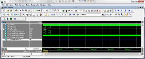
- Mark as New
- Bookmark
- Subscribe
- Mute
- Subscribe to RSS Feed
- Permalink
- Report Inappropriate Content
Hi,
I got the similar design logic to work on ModelSim Intel edition and Quartus 17.1 (with latest updates) . Here's the code ;
module plltest (
            Clock,
            Reset,
            Locked,
            CountOut
            );

input             Clock;
input             Reset;
output         Locked;
output         CountOut;
wire  CountOut;
wire         Locked;
reg    Count;
wire         PLL_clock;
pll_1 counter_pll (
            .refclk   (Clock),
            .rst         (~Reset),
            .locked   (Locked),
            .outclk_0(PLL_clock)
            );
always@(posedge PLL_clock or negedge Reset) begin
  if (~Reset) begin
     Count <= 4'b0000;
  end
  else begin
    if(Locked) begin
       Count <= Count + 4'b0001;
    end
    else begin
       Count <= 4'b0000;
     end
  end
end //always
assign CountOut = Count;
endmodule
The PLL locked at the input clock, Locked port went high and the counter output was generated. I've included the QAR file, you could extract it and check it out. The device used is Cyclone 5 GX, so the PLL used is Altera_PLL. I'll be generating one more with the Cyclone10LP device and the ALTPLL function as well. - Abr
- Mark as New
- Bookmark
- Subscribe
- Mute
- Subscribe to RSS Feed
- Permalink
- Report Inappropriate Content
Hi,
Just tried with the ALTPLL function and the output clock is not being generated. This is definitely a sim model issue and needs to be fixed by Altera. Thanks for pointing it out. -Abr- Mark as New
- Bookmark
- Subscribe
- Mute
- Subscribe to RSS Feed
- Permalink
- Report Inappropriate Content
Thanks very much for taking the time to verify that it doesn't work! It would have been simple to have left it without trying the 10 LP and ALTPLL, and I would have spent a bunch of time fruitlessly trying to replicate your results in my environment. I'm glad to know that I'm not (completely) crazy or a (complete) moron. :)
Any suggestions for tricking a testbench into generating the PLL output clock without changing the synthesized code? I suppose I could just create a version with an input clock to the FPGA that replaces the PLL output for functional testing, but the timing would likely be totally whacked. And please advise on the estimated timeframe for the simulator fix. I know that's asking a lot. Thanks again!- Mark as New
- Bookmark
- Subscribe
- Mute
- Subscribe to RSS Feed
- Permalink
- Report Inappropriate Content
Hi,
--- Quote Start --- Thanks very much for taking the time to verify that it doesn't work! It would have been simple to have left it without trying the 10 LP and ALTPLL, and I would have spent a bunch of time fruitlessly trying to replicate your results in my environment. I'm glad to know that I'm not (completely) crazy or a (complete) moron. :) Any suggestions for tricking a testbench into generating the PLL output clock without changing the synthesized code? I suppose I could just create a version with an input clock to the FPGA that replaces the PLL output for functional testing, but the timing would likely be totally whacked. And please advise on the estimated timeframe for the simulator fix. I know that's asking a lot. Thanks again! --- Quote End --- Yes we acknowledged this bug/issue and has been reported to the engineering team. however you can run cyclone 10 lp altpll vhdl simulation model in quartus v17.0 and v17.1.it works fine Let me know if this has helped resolve the issue you are facing or if you need any further assistance. Best Regards, Anand Raj Shankar (This message was posted on behalf of Intel Corporation)
- Mark as New
- Bookmark
- Subscribe
- Mute
- Subscribe to RSS Feed
- Permalink
- Report Inappropriate Content
Hi,
Please check the below link the problem has been addressed. https://www.altera.com/support/suppo...-lp-pll-i.html Best Regards, Anand Raj Shankar (This message was posted on behalf of Intel Corporation)- Subscribe to RSS Feed
- Mark Topic as New
- Mark Topic as Read
- Float this Topic for Current User
- Bookmark
- Subscribe
- Printer Friendly Page