- Mark as New
- Bookmark
- Subscribe
- Mute
- Subscribe to RSS Feed
- Permalink
- Report Inappropriate Content
Hi,
I'm using GTS AXI Streaming intel FPGA IP for PCI Express to implement PCIe on Agilex 5 FPGA (A5ED065BB32AE4 ,Quartus Prime 25.1) . I connect Pin p0_pin_perst_n_i to a 3.3v pll up resistance on the board while pin p0_pin_perst_n_1_i is left floating . When testing on the board , p0_pin_perst_n remains asserted and the p0_reset_status_n remains low . It seems like the IP cannot jump out off reset . I wonder what may cause this situation and how can i solve the problem .
I also tried to simulate the ip in Questa intel FPGA . I found that p0_pin_perst_n deasserted correctly after system PLL got locked in simulation .The simulation and the on board testing i made were using the same top module .Here is my testing project .
Many thanks,
Chester
Link Copied
- Mark as New
- Bookmark
- Subscribe
- Mute
- Subscribe to RSS Feed
- Permalink
- Report Inappropriate Content
Hi Chester,
Thanks for reaching out.
Could you please address the following items?
- May I know what board/dev kit you use?
- Could you confirm the pin assignments are correct?
- Could you try to use the PIO Design Example generated directly from Quartus?
- Have you tried to bring up the PCIe using the same design example in the previous Quartus versions?
- What is the hardware setup and the procedures you performed to capture the STP? Have you rebooted the workstation/PC after programming the SOF?
- From the STP you shared, the PCIe IP is out of reset. Could you capture the STP using Type: Transitional in the storage qualifier settings?
Thanks.
Best Regards,
Ven
- Mark as New
- Bookmark
- Subscribe
- Mute
- Subscribe to RSS Feed
- Permalink
- Report Inappropriate Content
Hi Ven,
Thanks for your reply !
I'm sorry for getting back to you late .
1. The board i use is AXE5-Eagle made by Arrow , not a Intel dev kit .
2. I confirm the pin assignments are correct . I'll post some related parts of schematic diagram in the following pictures .
3. Now i'm using a PIO Design Example generated directly from Quartus . But the situation is just the same .
4. I've never tried to do that since there is no other version of Quartus installed on my PC .
5. I didn't Insert the PCIe board into the motherboard everytime when testing. But when i did that , i did reboot the PC after
programming the SOF .
6. The pin p0_pin_perst_n is low and LTSSM stuck on state 0 , is that normal ? I tried to capture the STP using Type: Transitional in the storage qualifier settings but it didn't work .
Best Regards,
Chester
- Mark as New
- Bookmark
- Subscribe
- Mute
- Subscribe to RSS Feed
- Permalink
- Report Inappropriate Content
Hi Chester,
Good day.
Could you please get back to us on the previous message?
Thanks.
Best Regards,
Ven
- Mark as New
- Bookmark
- Subscribe
- Mute
- Subscribe to RSS Feed
- Permalink
- Report Inappropriate Content
Hi Chester,
Thank you for providing the updates, and my apologies for the late reply.
5. I didn't Insert the PCIe board into the motherboard everytime when testing.
Could you clarify this? My understanding is that the PCIe board (Arrow Eagle board) is always inserted into the motherboard, and you test by programming the SOF and rebooting the PC.
6. The pin p0_pin_perst_n is low and LTSSM stuck on state 0 , is that normal ? I tried to capture the STP using Type: Transitional in the storage qualifier settings but it didn't work .
No, p0_pin_perst_n should toggle from low to high, and then LTSSM should eventually reach h11 (L0 state). You can capture this using STP with Transitional settings. What are the errors you encountered when setting the storage qualifier to Transitional?
Thanks.
Best Regards,
Ven
- Mark as New
- Bookmark
- Subscribe
- Mute
- Subscribe to RSS Feed
- Permalink
- Report Inappropriate Content
Hi Ven,
I thought that the pcie ip would reset itself when the board powers on and the pin PERST# is always high (tied to a pull-up resistance) so i don't have to insert the board into the motherboard before . I realized that it is not right so i now insert the board into the motherboard everytime when testing .
Sorry for misleading you . What i meant is i captured the STP after setting the storage qualifier type to transitional , p0_pin_perst_n still didn't toggle from low to high .
Best Regards,
Chester
- Mark as New
- Bookmark
- Subscribe
- Mute
- Subscribe to RSS Feed
- Permalink
- Report Inappropriate Content
Hi Chester,
I could not view the full signals from the attached image (2025-08-18_103808_129.png).
Could you please follow these steps to capture the signals? Please use the Design Example generated from Quartus without modifying the design (only add STP and pin assignments for the Eagle board):
1.Power on the PC (the board powers on at the same time).
2. Program the .sof file.
3.Start capturing the Transitional Signal Tap instance (click Run Analysis).
4.Reboot the PC.
5.When the PC is up, stop the Signal Tap capture (click Stop Analysis).
Please make sure the pin assignments for refclk and PERST# are correct.
Have you ever observed p0_pin_perst_n toggling from low to high?
Thanks.
Best Regards,
Ven
- Mark as New
- Bookmark
- Subscribe
- Mute
- Subscribe to RSS Feed
- Permalink
- Report Inappropriate Content
Hi Ven,
Thanks for your reply !
What else signals do you need to see to help me out ?
I use the Design Example generated from Quartus only with these modifications .
1. I change the frequency of IOPLL refclk from 100Mhz to 25Mhz .
2. I add STP and pin assignments for the Eagle board .
I followed your guide but i have never observed p0_pin_perst_n toggling from low to high still .
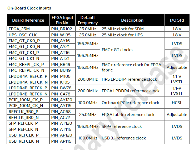
I checked the pin assignments for refclk and PERST# and found nothing wrong with them . I will post some parts of user guide of the Eagle board in the following pictures so you can help me check .
Best Regards,
Chester
- Subscribe to RSS Feed
- Mark Topic as New
- Mark Topic as Read
- Float this Topic for Current User
- Bookmark
- Subscribe
- Printer Friendly Page